Building Envelope (BE)
Overview of the Building Envelope Checks
Building Envelope group of checks addresses above and below grade walls and floors, roof, fenestration, infiltration, building orientation and exterior and interior shading. Table 5 summarizes the checks included in this group.
For 90.1 2022 PRM alterations subject to G3.3 (i.e., Minor alterations), the summary tables on the Quality Control Checks tab in the Compliance Form may not reflect correct values for the baseline since projects, for the most part, only enter proposed design information and provide notes as to what was modeled in the baseline in the notes fields associated with the proposed design related tables. Refer to the 90.1 2022 Section G3.3 Performance Calculations for Other Alterations section for more information regarding 90.1 2022 G3.3.
Table 5: Building Envelope Checks Overview
| Focus of the Check | Type of Check | Proposed Design | Baseline/Budget Design |
|---|---|---|---|
| Above-grade wall | CF inputs reflect design documents | BE01-P | NA |
| General requirements of ECB/PRM | NA | BE01-B | |
| Simulation inputs consistent with CF | BE06-P | BE06-B | |
| Simulation outputs consistent with CF | BE19 | BE19 | |
| Below-grade Walls | CF inputs reflect design documents | BE02-P | NA |
| CF inputs reflect requirements of ECB/PRM | NA | BE02-B | |
| Simulation inputs consistent with CF | NA | BE02-B | |
| Simulation outputs consistent with CF | BE19 | BE19 | |
| Roof | CF inputs reflect design documents | BE03-P BE11-P | NA |
| CF inputs reflect requirements of ECB/PRM | NA | BE03-B BE11-B | |
| Simulation inputs consistent with CF | BE08-P BE04-P | BE08-B BE12-B | |
| Simulation outputs consistent with CF | BE19 | BE19 | |
| Exterior Floor | CF inputs reflect design documents | BE04-P | NA |
| CF inputs reflect requirements of ECB/PRM | NA | BE04-B | |
| Simulation inputs consistent with CF | BE09-P | BE09-B | |
| Simulation outputs consistent with CF | BE19 | BE19 | |
| Slab-on Grade | CF inputs reflect design documents | BE05-P | NA |
| CF inputs reflect requirements of ECB/PRM | NA | BE05-B | |
| Simulation inputs consistent with CF | BE10-P | BE10-B | |
| Simulation outputs consistent with CF | BE19-P | BE19 | |
| Fenestration | CF inputs reflect design documents | BE13-P BE15-P | NA |
| CF inputs reflect requirements of ECB/PRM | NA | BE13-B BE15-B | |
| Simulation inputs consistent with CF | BE14-P BE16-P | BE14-B BE16-B | |
| Simulation outputs consistent with CF | BE19 | BE19 | |
| Infiltration | CF inputs reflect design documents | BE17-P | NA |
| CF inputs reflect requirements of ECB/PRM | NA | BE17-B | |
| Simulation inputs consistent with CF | BE18-P | BE18-B | |
| Simulation outputs consistent with CF | BE19-P | BE19 | |
| Orientation | CF inputs reflect design documents | BE20-P | NA |
| CF inputs reflect requirements of ECB/PRM | NA | BE20-B | |
| Simulation inputs consistent with CF | BE21-P | BE22-B | |
| Interior/Exterior Shading | CF inputs reflect design documents | BE22-P | NA |
| CF inputs reflect requirements of ECB/PRM | NA | BE22-B | |
| Simulation inputs consistent with CF | BE23-P | BE23-B | |
| All Components | CF inputs reflect requirements of ECB/PRM | BE24-P | NA |
| Legend: PASS/FAIL/NA outcome is determined automatically in the Quality Control Checks tab of the Compliance Form. | |||
The following strategies may be used to prioritize the review:
- Checks related to slab on grade floors and below grade walls are more important for low-rise buildings (e.g., 5 floors or less) where HVAC energy use is envelope-dominated such as in multifamily, hotels, motels, dormitories and schools. For other types of projects, it may be spot- checked or skipped.
- Focus on verifying constructions that account for the largest surface area and spot-check the rest. For these selected constructions, perform all types of checks listed in Table 5. To facilitate prioritization based on surface area, the Quality Control Checks tab of the Compliance Form includes a table showing the three constructions accounting for the largest area within each surface type (exterior wall, roof, floor, etc.)
- The review of fenestration should similarly focus on window products accounting for the largest area. Refer to the table on the Quality Control Checks tab, Building Envelope section for the fenestration types sorted by area.
- Roof and exterior wall reflectance has a higher impact in cooling-dominated climates such as Climate Zones 0-4 and may be spot-checked or skipped for projects in other climate zones.
- Interior and exterior shading has a higher impact in cooling-dominated climates such as Climate Zones 0-4 and may be spot-checked or skipped for projects in other climate zones.
BE01-B Thermal properties of the baseline/budget above-grade walls are established correctly.
See BE05-B for section references and review tips as they are analogous for all opaque assemblies.
BE02-B Thermal properties of the baseline/budget below-grade walls are established correctly.
See BE05-B for section references and review tips as they are analogous for all opaque assemblies.
BE03-B Thermal properties of the baseline/budget roof are established correctly.
See BE05-B for section references and review tips as they are analogous for all opaque assemblies.
BE04-B Thermal properties of the baseline/budget exterior floors are established correctly.
See BE05-B for section references and review tips as they are analogous for all opaque assemblies.
BE05-B Thermal properties of the baseline/budget slab-on-grade floor are established correctly.
90.1 2016 and 2019 ECB
Table 11.5.1#5a, Column B:The opaque assemblies, such as roof, floors, doors and walls must be modeled with the same heat capacity (the same construction) as the proposed building design and the U-factors in 90.1 Section 5.5 for new buildings or additions and 90.1 Section 5.1.3 (5.1.4 in 90.1 2022) for alterations. When trade-offs are made between an addition and an existing building as described in the exception to Section 4.2.1.2, the envelope in the budget building design must reflect existing conditions prior to any retrofits that are part of the permit. Unconditioned envelope components must be modeled with the same properties as specified in the proposed design.
90.1 2022 ECB
12.5.1 #5a, Column B has similar requirements to Table 11.5.1#5a, Column B described above. However, 90.1 2022 specifically includes requirements for adjusting above grade wall U-factors in the budget model to account for linear thermal bridges and point thermal bridges. 12.5.1 #5b, Column B: Where linear thermal bridges and point thermal bridges, as identified in Sections 5.5.5.1 through 5.5.5.5, are included in the proposed design, they must be modeled by adjusting the U-factor of the parent assembly in accordance with the default values in Section A10. If the proposed design does not have linear thermal bridges and point thermal bridges, as identified in Sections 5.5.5.1 through 5.5.5.5, they do not have to be modeled in the budget building design. If the balcony length in the proposed design exceeds the maximum allowed by Sections 5.5.5.2.2, the area must be reduced proportionally for each balcony until the limit set in Sections 5.5.5.2.2 is met.
90.1 2016 and 2019 PRM
Table G3.1 #5, Baseline Building Performance column: Opaque assemblies of new buildings, existing buildings, or additions shall conform with assemblies detailed in 90.1 Appendix A and match the appropriate assembly maximum U-factors in 90.1 Tables G3.4-1 through G3.4-8:
- Roofs—Insulation entirely above deck (90.1 Section A2.2).
- Above-grade walls—Steel-framed (90.1 Section A3.3).
- Below-grade walls—Concrete block (90.1 Section A4).
- Floors—Steel-joist (90.1 Section A5.3).
- Slab-on-grade floors shall match the F-factor for unheated slabs from the same tables (90.1 Section A6).
Unconditioned envelope components must be modeled in the baseline with the same properties as specified in the proposed design.
90.1 2022 PRM
G3.2 New Construction/Major AlterationsRequirements are similar to 90.1 2016 and 2019 PRM requirements described above. An addition is that the process of establishing the space conditioning category was clarified in 90.1 2022. Table G3.1 #5b, Baseline Building Performance column: Space conditioning categories used to determine applicability of the envelope requirements in Tables G3.4-1 through G3.4-8 shall be the same as in the proposed design
Exception: Envelope components of the HVAC zones that are semiheated in the proposed design must meet conditioned envelope requirements in Tables G3.4-1 through G3.4-8 if, based on the sizing runs, these zones are served by a baseline system with sensible cooling output capacity ≥5 Btu/h·ft2 of floor area, or with heating output capacity greater than or equal to the criteria in Table G3.4-9, or that are indirectly conditioned spaces.
G3.3 Minor AlterationsThe opaque assemblies included in the scope of retrofit for alterations subject to 90.1 2022 G3.3 (i.e., minor alterations not meeting G3.1.4a) shall be modeled with U-factors meeting the requirements in Section 5.1.4 (see errata sheet for ANSI/ASHRAE/IES STANDARD 90.1-2022 for correction from 5.1.3 to 5.1.4) as prescribed in 90.1 Section G3.3.2.3.
Review Tips
- Baseline/budget assembly U/F/C factors are auto populated in Table 1 of the Envelope Areas tab
of the Compliance Form based on the space conditioning categories specified by the user. Thus,
the review should focus on verifying that the building envelope conditioning categories are
established correctly, with the focus on the above-grade exterior walls that account for the
greatest area. (The ranking of exterior walls by area is shown in the Quality Controls Checks
tab, Building Envelope (BE) area. Refer to
90.1 2022 Section G3.3 Performance Calculations for Other Alterations
for tips for alterations subject to 90.1 2022 Section G3.3 (i.e., Minor alterations).
The selection should be based on the following criteria:
- Residential surface bounds residential space and must be classified as exterior building envelope
- Nonresidential surface bounds nonresidential space and is classified as exterior building envelope
- Semiheated surface is classified as semiexterior building envelope
- All other surfaces are classified as unconditioned.
90.1 Section 3: Residential vs non-residential spaces- Residential spaces are “spaces in buildings used primarily for living and sleeping. Residential spaces include, but are not limited to, dwelling units, hotel/motel guest rooms, dormitories, nursing homes, patient rooms in hospitals, lodging houses, fraternity/sorority houses, hostels, prisons, and fire stations.”
- All other enclosed spaces are classified as non-residential.
- Unenclosed spaces include crawlspaces, attics, and parking garages with natural or mechanical ventilation and are treated as exterior when determining applicable envelope requirements
90.1 Section 3 and Figure 5.5.2: Exterior vs semi-exterior building envelope- Exterior Building Envelope: the elements of a building that separate conditioned spaces from the exterior
- Semiexterior Building Envelope: the elements of a building that separate conditioned space from unconditioned space or that enclose semiheated spaces through which thermal energy may be transferred to or from the exterior, to or from unconditioned spaces, or to or from conditioned spaces.
- Spaces may be classified as conditioned (cooled, heating or indirectly conditioned), semiheated, unconditioned or unenclosed. See definition of the space in 90.1 Section 3 for more details.
- Common examples of conditioned spaces include offices, classrooms, hotel guestrooms, etc. Common examples of semiheated spaces include storage areas.
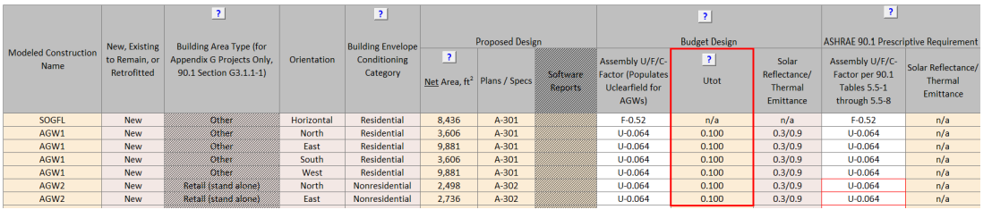
- For 90.1 2022 ECB projects, budget assembly U factors accounting for linear and point thermal
bridging are manually entered in Table 1 of the Envelope Areas tab of the Compliance Form in the
column labeled Utot. The Submittal Checklist on the Submittal+Mand.Req. Checklists tab in the
Compliance Form requests that the submitter provide supporting documentation/calculations in
accordance with the default values in 90.1 2022 Section A10 for establishing the Utot values
modeled in the budget design model. Confirm that the supporting documentation/calculations Utot
values align with the values entered in Table 1 and that values were established in accordance
with the default values in Section A10. Note that alterations other than additions are exempt
from thermal bridging requirements according to Standard 90.1-2022 Section 5.5.5 exception #6.
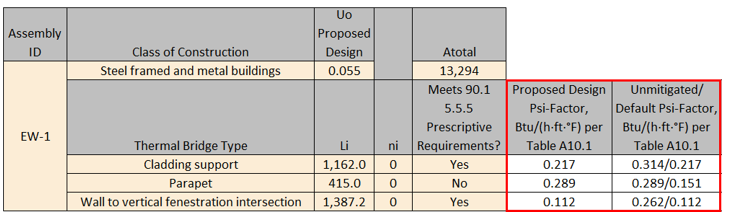
A 33,000 square foot, 4-story multifamily building includes thermal bridging due to brick shelf angle cladding support, a parapet that follows the entire perimeter of the roof, and wall to vertical fenestration intersections. Below is a high-level graphical depiction showing the location of these thermal bridges. The length of the parapet would equal the perimeter of the building since it runs along the edge of the roof, the brick shelf angles run continuously along the perimeter once per floor so the total linear length would be the perimeter of the building multiplied by 4-stories, and the length of the wall to vertical fenestration would be the sum of the perimeter of each window as depicted with the yellow lines around the perimeter of the window shown in the graphic below.
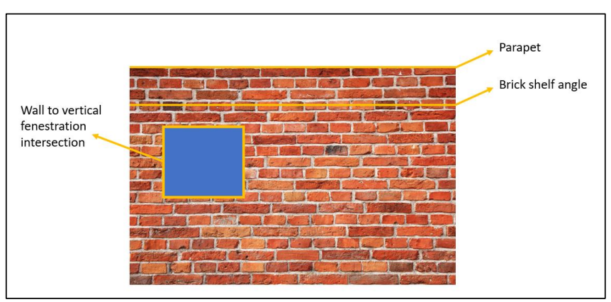
The design team needs to quantify the length of each linear thermal bridge as measured on the outside surface of the building envelope (Li) and the number of occurrences of each type of point thermal bridge (ni). Below, outlined in red, is an example of the minimum information needed to determine the budget U-factor to model for example assembly EW-1. This process would need to be completed for all above grade wall assemblies. Project teams can use the built-in functionality in Comcheck for 90.1 2022 to complete and document these calculations.
The budget Utot is calculated using equation 90.1 2022 A10.2 which is shown directly below.
Utot = {[(∑ψi × Li) + (∑χj × nj)]/Atotal) + Uo}
Where
Utot = overall thermal transmittance, including the effect of linear thermal bridges and point thermal bridges not included in the construction assembly Uo-factor, Btu/(h·ft2·°F)
Uo = clear-field thermal transmittance of the construction assembly as determined from 90.1 2022 Tables 5.5, 0-8 based on the proposed design assembly type, Btu/(h·ft2·°F)
Atotal = total opaque projected surface area of the construction assembly, ft2
ψi = psi-factor, thermal transmittance for each type of linear thermal bridge from 90.1 2022 Table A10.1 “Default” column, Btu/(h·ft·°F)
Li = length of a particular linear thermal bridge as measured on the outside surface of the building envelope, ft
χi = chi-factor, thermal transmittance for each detail type of point thermal bridge from 90.1 2022 Table A10.1 “Default” column, Btu/(h·°F)
ni = number of occurrences a particular type of point thermal bridge
Below, outlined in red, shows the Psi-factor from both the Unmitigated column and the Default column from 90.1 2022 Table A10.1 (left value is unmitigated and right is default). The chi-factors are not shown because they are not applicable to the thermal bridging types shown in the table.
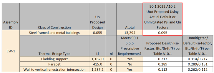
Using equation A10.2 the Utot required to be modeled in the budget design model is calculated as follows:
Utot budget for EW-1 = 0.064 + [(1,162 ft * 0.217 Btu/(h·ft·°F)) + (415 ft* 0.151 Btu/(h·ft·°F)) + (1,387.2 ft * 0.112 Btu/(h·ft·°F))]/13,294 ft2 = 0.064 + 0.0353 = 0.099 Btu/(h·ft2·°F)
Below is an example format for complete documentation/supporting calculations. These calculations would need to be submitted for each above grade wall assembly. The chi-factors are not shown because they are not applicable to the thermal bridging types shown in the table. For this review check the proposed design related columns can be ignored. Project teams can use the built-in functionality in Comcheck for 90.1 2022 to complete and document these calculations.
For this review check spot check the calculations for alignment with 90.1 2022 equation A10.2 and compare Li and ni inputs to design documents to ensure they have been captured correctly in the calculations.
Common Mistakes
- Floors of conditioned spaces adjacent to garages must be treated as exterior surfaces when establishing the baseline floor U-value, as garages are considered un-enclosed spaces.
- Treating the envelope of residential spaces in non-residential buildings as non-residential envelope. For example, even though hospitals are considered non-residential building type, patient rooms are used primarily for living and sleeping, and are thus residential spaces.
BE01-P Thermal properties of the exterior walls in the proposed design are established correctly.
90.1 2016 and 2019 ECB
Table 11.5.1 #5 Column AAll components of the building envelope in the proposed design must be modeled as shown on architectural drawings or as installed for existing building envelopes. Any building envelope assembly that covers less than 5% of the total area of that assembly type (e.g., exterior walls) need not be separately described. If not separately described, the area of a building envelope assembly must be added to the area of the adjacent assembly of that same type.
90.1 2022 ECB
Requirements of Table 12.5.1 #5 Column A are similar to Table 11.5.1 #5 Column A above except for the addition of the following.
All linear thermal bridge and point thermal bridge as identified in Section 5.5.5 must be modeled using either of the following techniques:
- Separate model of each of these assemblies within the energy simulation model.
- Adjustment of the clear-field U-factor in accordance with Section A10.2.
All uninsulated assemblies (e.g., projecting balconies, perimeter edges of intermediate floor stabs, concrete floor beams over parking garages, roof parapet) must be separately modeled using either of the following techniques:
- Separate model of each of these assemblies within the energy simulation model.
- Separate calculation of the U-factor for each of these assemblies. The U-factors of these assemblies are then averaged with larger adjacent surfaces using an area-weighted average method. This average U-factor is modeled within the energy simulation model.
90.1 2016 and 2019 PRM
Table G3.1 #5 (a), Proposed Building Performance columnAll components of the building envelope in the proposed design must be modeled as shown on architectural drawings or as built for existing building envelopes.
All uninsulated assemblies (e.g., projecting balconies, perimeter edges of intermediate floor stabs, concrete floor beams over parking garages, roof parapet) must be separately modeled using either of the following techniques:
- Separate model of each of these assemblies within the energy simulation model.
- Separate calculation of the U-factor for each of these assemblies. The U-factors of these assemblies are then averaged with larger adjacent surfaces using an area-weighted average method. This average U-factor is modeled within the energy simulation model.
Any other building envelope assembly that covers less than 5% of the total area of that assembly type (e.g., exterior walls) need not be separately described, provided that it is similar to an assembly being modeled. If not separately described, the area of a building envelope assembly must be added to the area of an assembly of that same type with the same orientation and thermal properties.
90.1 2022 PRM
Requirements are similar to 90.1 2016 and 2019 PRM Table G3.1 #5 (a), Proposed Building Performance column requirements above except for the addition of the following.
All linear thermal bridge and point thermal bridge as identified in Section 5.5.5 must be modeled using either of the following techniques:
- Separate model of each of these assemblies within the energy simulation model.
- Adjustment of the clear-field U-factor in accordance with Section A10.2.
Review Tips
-
Locate constructions selected for the review in the design documents based on the reference
provided for that construction in the Plans/Specs column of Table 1 in the Proposed Envelope
Assemblies tab of the Compliance form (note that some columns may be hatched out and table
headings may vary depending on the applicable version of 90.1 since requirements differ across
vintages). Focus the review on constructions that account for the highest wall area, as shown in
the table in the Building Envelope (BE) section of the Quality Control Check tab.
- Verify that the description of the construction provided in the table reflects design documents. The location in the design documents where construction is described is included in the last column of Table 1 in the Proposed Envelope Assemblies tab of the Compliance Form shown above.
-
Verify that the value reported in “Modeled U/C/F-factor Including Int. and Ext. Air Film” is
established correctly. (See Common Mistakes section.)
For 90.1 2022 PRM and ECB projects, the proposed assembly U factors are required to account for linear and point thermal bridging, so Uclearfield needs to be derated and the resultant derated U-factor entered in the “Modeled U/C/F-factor Including Int. and Ext. Air Film” column. Uclearfield is entered in the “Uclearfield” column. Clear-field thermal bridges (90.1 Section 3) are elements of a building envelope assembly that are distributed over the area of the assembly and addressed in determining the thermal performance of the assembly in accordance with Normative Appendix A (i.e., U-factors determined from Appendix A tables are considered Uclearfield and need to be adjusted for linear and point thermal bridging).
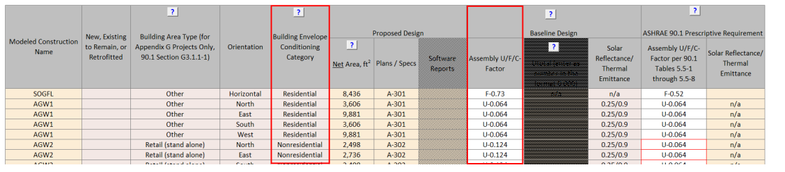
The Submittal Checklist on the Submittal+Mand.Req. Checklists tab in the Compliance Form requests that the submitter provide supporting documentation/calculations for the modeled U-factors that account for linear and point thermal bridging. Confirm that the supporting documentation/calculations align with the U-factor values entered in Table 1. If “Adjustment of the clear-field U-factor in accordance with Section A10.2” was selected in the “Technique to Capture Linear and Point Thermal Bridging” column, verify that values were established in accordance with Section A10.2. If “A separate model of the assembly within the energy simulation model" was selected in the “Technique to Capture Linear and Point Thermal Bridging” column, refer to Envelope Areas tab Table 1 to confirm that the reported Net Area for such assemblies is appropriate.
Example BE01-P: Project that is adjusting the clear-field U-factor in accordance with Section A10.2See Example BE05-B for description of example project, assembly, and assembly thermal bridges. The same assembly and set of thermal bridges are used for this example.
Like in Example BE05-B, the design team needs to quantify the length of each linear thermal bridge as measured on the outside surface of the building envelope (Li) and the number of occurrences of each type of point thermal bridge (ni). Below is an example of the minimum information needed to determine the proposed U-factor to model (Utot) for example assembly EW-1. This process would need to be completed for all above grade wall assemblies. Project teams can use the built-in functionality in Comcheck for 90.1 2022 to complete and document these calculations.

The proposed Utot is calculated using equation 90.1 2022 A10.2 which is shown directly below.
Utot = {[(∑ψi × Li) + (∑χj × nj)]/Atotal) + Uo}
Where
Utot = overall thermal transmittance, including the effect of linear thermal bridges and point thermal bridges not included in the construction assembly Uo-factor, Btu/(h·ft2·°F)
Uo = clear-field thermal transmittance of the construction assembly as determined in accordance with Section 5, Btu/(h·ft2·°F)
Atotal = total opaque projected surface area of the construction assembly, ft2
ψi = psi-factor, thermal transmittance for each type of linear thermal bridge from 90.1 2022 Table A10.1. The default column shall be used where the thermal bridge meets 90.1 Section 5.5.5 prescriptive requirements. The unmitigated column shall be used where the thermal bridge does not meet the prescriptive requirements., Btu/(h·ft·°F)
Li = length of a particular linear thermal bridge as measured on the outside surface of the building envelope, ft
χi = chi-factor, thermal transmittance for each detail type of point thermal bridge from 90.1 2022 Table A10.1. The default column shall be used where the thermal bridge meets 90.1 Section 5.5.5 prescriptive requirements. The unmitigated column shall be used where the thermal bridge does not meet the prescriptive requirements., Btu/(h·°F)
ni = number of occurrences a particular type of point thermal bridge.
The “Proposed Design Psi-Factor, Btu/(h·ft·°F) per Table A10.1” column in the graphic below shows the Psi-factor used in the calculation of Utot for the proposed design for this example assembly. This is determined based on whether the specified thermal bridging mitigation techniques (if any are specified) meet the prescriptive requirements in 90.1 Section 5.5.5. If the specified thermal bridging mitigation techniques do not meet prescriptive requirements, then the unmitigated column in Table A10.1 must be used. For reference only, the “Unmitigated/Default Psi-Factor, Btu/(h·ft·°F) per Table A10.1” column below shows both the Unmitigated and Default columns from 90.1 2022 Table A10.1 (left value is unmitigated and right is default). The chi-factors are not shown because they are not applicable to the thermal bridging types shown in the table.
Using equation A10.2 the proposed Utot required to be modeled in the proposed design model for this example assembly is calculated as follows:
Utot proposed for EW-1 = 0.055 + [(1,162 ft * 0.217 Btu/(h·ft·°F)) + (415 ft* 0.289 Btu/(h·ft·°F)) + (1,387.2 ft * 0.112 Btu/(h·ft·°F))]/13,294 ft2 = 0.055 + 0.0353 = 0.095 Btu/(h·ft2·°F)
Below is an example format for complete documentation/supporting calculations. These calculations would need to be submitted for each above grade wall assembly. The chi-factors are not shown because they are not applicable to the thermal bridging types shown in the table. Project teams can use the built-in functionality in Comcheck for 90.1 2022 to complete and document these calculations.
Spot check the calculations for alignment with 90.1 2022 equation A10.2, compare Li and ni inputs to design documents, and verify that the project complies with prescriptive thermal bridging mitigation requirements in Section 5.5.5 where default psi and chi factors are used.
-
Review architectural details drawing to identify if project includes any uninsulated assemblies
such as projecting balconies, perimeter edges of intermediate floor stabs, concrete floor beams
over parking garages and roof parapets (for 90.1 2022 projects many of these may already be
captured as linear and/or point thermal bridges). If present, check “Modeled U/C/F-Factor
Includes Uninsulated Assemblies?” column to confirm that such elements were included with the
adjacent constructions with the appropriate adjustment to overall U-factor (based on
area-weighted average) or reported as separate construction. If separately reported, refer to
Envelope Areas tab Table 1 to confirm that the reported Net Area for such assemblies is
appropriate.
- Common Mistakes
-
The overall assembly U-value is established without accounting for clear-field thermal
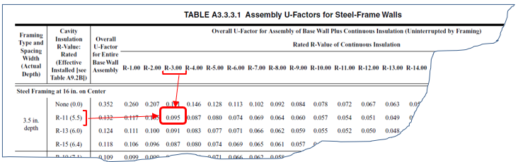
bridging, as required by 90.1 Section 5.5.3. For example, a steel framed wall assembly
with R-13 insulation in the 16” on center steel framing cavity and R-3 continuous
insulation must be reported as U-0.091.
- For tapered roof insulation, the U-value should be based on the area-weighted average R-Value for the varying insulation thickness (see Standard 90.1 2016 User’s Manual Example FY1, Area Weighted Averages).
- For 90.1 2022 projects, failure to account for linear and point thermal bridging following the requirements for the ECB and PRM.
-
The overall assembly U-value is established without accounting for clear-field thermal
bridging, as required by 90.1 Section 5.5.3. For example, a steel framed wall assembly
with R-13 insulation in the 16” on center steel framing cavity and R-3 continuous
insulation must be reported as U-0.091.
BE02-P Thermal properties of the proposed below-grade walls are established correctly.
Review Tips
- The QC check may be skipped for projects with small below-grade wall area.
- See BE01-P for additional tips.
BE03-P Thermal properties of the proposed roof are established correctly.
See BE01-P for additional tips.
BE04-P Thermal properties of the proposed exterior floors are established correctly.
Review Tips
- Majority of projects that include garage on lower floors are expected to have this surface type as garages are typically classified as un-enclosed spaces (which is equivalent to ambient conditions for envelope compliance purposes) and the floor separating garage from conditions spaces above should be insulated appropriately.
- See BE01-P for additional tips.
BE05-P Thermal properties of the proposed slab-on-grade floor are established correctly.
Review Tips
- Unless a project includes a portion of the building over conditioned spaces (e.g., floors 3-10 of a building that has conditioned 2nd floor), it is expected to have exposed floors, slab-on-grade, or below-grade walls. (Slab below grade does not have to be reported). If neither of these surfaces are included in the Compliance Form, a comment should be made to request that missing surfaces are reported in the Compliance Form and modeled.
- See BE01-P for additional tips.
BE06-B, BE06-P Modeled U-factors and areas of the baseline/budget and proposed above-grade walls are as reported in the Compliance Form.
Review Tips
- Use simulation reports to verify that modeled U-factors and areas of the exterior walls reflect
the values reported in the Compliance Form. The reported values are located in the following
tables within the Compliance Form:
- Baseline/budget design: Table 1 in the Envelope Areas tab
- Proposed Design: Table 1 in the Proposed Envelope Assemblies tab.
- Focus on constructions that account for the largest above grade wall area based on the table in the Building Envelope section of the Quality Control Checks tab.
- Small deviations (e.g. up to 3%) between the value reported in the Compliance Form and simulation output reports may be accepted as it is often due to the contribution of the exterior air film. The prescriptive U-factors included in 90.1 Section 5 are based on the exterior air film R-values listed in 90.1 Appendix A (e.g., R-0.17 for roof constructions), while simulation tools may determine it dynamically based on the hourly weather conditions.
BE07-B, BE07-P Modeled C-factors and areas of the baseline/budget and proposed below-grade walls are as reported in the Compliance Form.
- Use simulation reports to verify that modeled C-factors and areas of the below-grade walls
reflect the values reported in the Compliance For. The reported values are located in the
following tables within the Compliance Form:
- Baseline/budget design: Table 1 in the Envelope Areas tab.
- Proposed Design: Table 1 in the Proposed Envelope Assemblies tab.
- Focus on constructions that account for the largest below grade wall area based on the table in the Building Envelope section of the Quality Control Checks tab.
- The QC check may be skipped for projects with relatively small area of below-grade walls.
BE08-B, BE08-P Modeled U-factors and areas of the baseline/budget and proposed roof are as reported in the Compliance Form.
- Use simulation reports to verify that modeled U-factors and areas of the roof reflect the
values reported in the Compliance For. The reported values are located in the following tables
within the Compliance Form:
- Baseline/budget design: Table 1 in the Envelope Areas tab.
- Proposed Design: Table 1 in the Proposed Envelope Assemblies tab.
- Focus on constructions that account for the largest roof area based on the table in the Building Envelope section of the Quality Control Checks tab.
BE09-B, BE09-P Modeled U-factors and areas of the baseline/budget floor is as reported in the Compliance Form
- Use simulation reports to verify that modeled U-factors and areas of the floor reflect the
values reported in the Compliance For. The reported values are located in the following tables
within the Compliance Form:
- Baseline/budget design: Table 1 in the Envelope Areas tab.
- Proposed Design: Table 1 in the Proposed Envelope Assemblies tab.
- Focus on constructions that account for the largest floor area based on the table in the Building Envelope section of the Quality Control Checks tab.
BE10-B, BE10-P Modeled F-factors and areas of the baseline/budget slab-on-grade are as reported in the Compliance Form.
- Use simulation reports to verify that modeled U-factors and areas of the floor reflect the
values reported in the Compliance Form. The reported values are located in the following tables
within the Compliance Form:
- Baseline/budget design: Table 1 in the Envelope Areas tab.
- Proposed Design: Table 1 in the Proposed Envelope Assemblies tab.
- Focus on constructions that account for the largest floor area based on the table in the Building Envelope section of the Quality Control Checks tab.
- The QC check may be skipped for projects involving buildings over 5 floors.
BE11-B Baseline/Budget roof and above grade wall reflectance and thermal emittance are established correctly in the Compliance Form
90.1 2016 and 2019 ECB
Table 11.5.1 Column A No 5 (b).The exterior roof surfaces shall be modeled with a solar reflectance and thermal emittance as required in Section 5.5.3.1.1(a). All other roofs, including roofs exempted from the requirements in Section 5.5.3.1.1, shall be modeled the same as the proposed design.
There is no baseline requirement for above grade walls so the solar reflectance and thermal emittance should be modeled identically in the budget and proposed design models.
90.1 2022 ECB
Table 12.5.1 Column A No 5 (b).- The exterior roof surfaces shall be modeled with a solar reflectance and thermal emittance as required in Section 5.5.3.1.4(a). All other roofs, including roofs exempted from the requirements in Section 5.5.3.1.4, shall be modeled the same as the proposed design.
- The above-grade wall surfaces of buildings shall be modeled with a solar reflectance and thermal emittance as required in Section 5.5.3.2.2 and 5.5.3.2.2(a). All other above-grade walls, including those exempt from the requirements in Section 5.5.3.2.2, shall be modeled the same as the proposed design.
90.1 2016 and 2019 PRM
Table G3.1 #5 Baseline Building Performance (f) and (g)- The exterior roof surfaces shall be modeled using a solar reflectance of 0.30 and a thermal emittance of 0.90.
- All roof surfaces shall be modeled with a reflectivity of 0.30.
There is no baseline requirement for above grade walls so the solar reflectance and thermal emittance should be modeled identically in the baseline and proposed design models.
90.1 2022 PRM
G3.2 New Construction/Major AlterationsTable G3.1 #5 Baseline Building Performance (h) and (i)
- The exterior roof surfaces shall be modeled using a solar reflectance of 0.30 and a thermal emittance of 0.90.
- Above-grade wall surfaces shall be modeled with a solar reflectance of 0.25 and a thermal emittance of 0.90.
For alterations subject to 90.1 2022 Section G3.3 (i.e., Minor alterations) roof and above grade wall reflectance and thermal emittance shall be modeled identically in the baseline and proposed design models since there are no applicable prescriptive or mandatory requirements in Section 5 for alterations.
Review Tips
- The related properties of the roof and above grade wall surfaces in the baseline/budget design are reported on the Envelope Areas tab Table 1. Over-written values are shown in bold brown.
- This QC check is important for projects located in cooling-dominated climates such as Climate Zones 0-4.
BE11-P Proposed design roof and above grade wall reflectance and thermal emittance reported in the Compliance Form reflect design documents
90.1 2016 and 2019 ECB
Table 11.5.1 Column A No 5 Exception 3.The exterior roof surface shall be modeled using the aged solar reflectance and thermal emittance determined in accordance with Section 5.5.3.1.1(a). Where aged test data are unavailable, the roof surface shall be modeled with a solar reflectance of 0.30 and a thermal emittance of 0.90.
90.1 2022 ECB
Table 12.5.1 Column A No 5 Exception 5.- The exterior roof surface shall be modeled using the aged solar reflectance and thermal emittance determined in accordance with Section 5.5.3.1.4(a). Where aged test data are unavailable, the roof surface shall be modeled with a solar reflectance of 0.30 and a thermal emittance of 0.90.
- The above-grade wall surfaces of buildings shall be modeled with an initial solar reflectance and thermal emittance determined in accordance with the test methods identified in Section 5.5.3.2.2(a). Where initial test data are unavailable, the above-grade wall surfaces shall be modeled with a solar reflectance of 0.25 and a thermal emittance of 0.90.
90.1 2016 and 2019 PRM
Table G3.1 #5 Proposed Building Performance (a)3- The exterior roof surface shall be modeled using the aged solar reflectance and thermal emittance determined in accordance with Section 5.5.3.1.1(a). Where aged test data are unavailable, the roof surface may be modeled with a reflectance of 0.30 and a thermal emittance of 0.90.
90.1 2022 PRM
Table G3.1 #5 Proposed Building Performance (a)5 and 8- The exterior roof surface shall be modeled using the aged solar reflectance and thermal emittance determined in accordance with Section 5.5.3.1.1(a). Where aged test data are unavailable, the roof surface may be modeled with a reflectance of 0.30 and a thermal emittance of 0.90.
- The above-grade wall surface shall be modeled using the initial solar reflectance and thermal emittance determined in accordance with the test methods identified in Section 5.5.3.2.2(a). Where initial test data are unavailable, the wall surface may be modeled with a solar reflectance of 0.25 and a thermal emittance of 0.90.
Review Tips
- Reflectance and emittance of the roof and above grade wall surfaces in the proposed design are reported in the Proposed Envelope Assemblies tab, Table 1.
- If reported reflectance/emittance differ from the default values above, refer to design documents to confirm the entered values or ask modeler for supporting documentation.
- This QC check is important for projects located in cooling-dominated climates such as Climate Zones 0-4.
BE12-B, BE12-P Baseline/Budget and proposed roof and above grade wall reflectance and thermal emittance are modeled as reported in the Compliance Form
Review Tips
Review simulation reports to verify that roof and above grade wall reflectance and thermal emittance values were modeled as reported in the Compliance Form.
BE13-B Fenestration area in the baseline/budget design is established correctly
90.1 2016 and 2019/2022 ECB
90.1 Table 11.5.1 #5 c/Table 12.5.1 #5 d: The budget building design must have identical exterior dimensions as the proposed design, except when the fenestration area of the new buildings or additions exceeds 40% of the gross exterior wall area, the budget fenestration area is reduced proportionally along each exposure until the total fenestration area is equal to 40%. Fenestration must be distributed on each face of the building in the same proportion as in the proposed design.
Exception: When trade-offs are made between an addition and an existing building, as described in Section 4.2.1.2.1, the budget building design shall reflect existing conditions, such as fenestration area, prior to any revisions that are part of the permit.
90.1 2016 and 2019 PRM
Table G3.1 #5 Baseline Building Performance column (c) and Table G3.1.1-1: The baseline fenestration area depends on the Building Area Type in Table G3.1.1-1. For example, a 40,000 ft2 office building is modeled with the baseline vertical fenestration area equal to 31% of the gross above grade wall area. For building types not specified in Table G3.1.1-1, such as multifamily, the baseline fenestration area shall be equal to that in the proposed design or 40% of the gross above-grade wall area, whichever is smaller. Fenestration must be distributed on each face of the building in the same proportion as in the proposed design.
Exception: The fenestration area for an existing building shall equal the existing fenestration area prior to the proposed work and shall be distributed on each face of the building in the same proportions as the existing building.
90.1 2022 PRM
Table G3.1 #5 Baseline Building Performance column (e) and Table G3.1.1-1 requirements are similar to Table G3.1 #5 Baseline Building Performance column (c) and Table G3.1.1-1 above except a clarification was added for the scenario in which distributing the vertical fenestration on each face of the building in the same proportion as in the proposed design would cause the combined vertical fenestration and opaque door area on a given face to exceed the gross above-grade wall area on that face. In this case, then the vertical fenestration area on other faces shall be increased in proportion to the gross above-grade wall area of these faces such that the total baseline building vertical fenestration area is equal to that calculated following Table G3.1.1-1.
Review Tips
- Baseline/budget fenestration area by exposure and building type is shown in the Envelope Areas tab Tables 3-5. The areas are automatically calculated by the Compliance Form by applying the appropriate rules of 90.1 to the project, but may be over-written by the modeler. If the default value was over-written, the input in the Fenestration Area, ft2 column is shown in light brown font. Over-ride may be justified for projects involving existing buildings where the baseline/budget fenestration must reflect area prior to retrofit or where distributing the fenestration on each face of the building in the same proportion as in the proposed design would cause the combined vertical fenestration and opaque door area on a given face to exceed the gross above-grade wall area on that face. The over-written values should be commented on, to request an explanation if one has not already been provided in the notes section.
-
Based on the 90.1 Definition section, all areas (including frame) that let in lighting, such as
windows, translucent plastic panels, doors that are more than one half glass and glass block
walls are considered fenestration.
Example: A multifamily project with 58,000ft2 gross wall area including 8,000 ft2 of operable windows, 5,000 ft2 of transparent glass block walls and 7,000 ft2 of spandrel, has fenestration area of 8,000 ft2 + 5,000 ft2 = 13,000 ft2 or 13,000 ft2/58,000 ft2=22% of gross exterior wall
BE13-P Fenestration area in the proposed design reported in the Compliance Form reflects design documents
90.1 2016 and 2019/2022 ECB
Table 11.5.1 No5, Column A/Table 12.5.1 No5, Column A:Fenestration area must be as shown on architectural drawings, or as installed for existing building envelopes.
90.1 2016, 2019, and 2022 PRM
Table G3.1 #5, Proposed Building Performance column:Fenestration area must be as shown on architectural drawings, or as installed for existing building envelopes.
Review Tips
-
The proposed fenestration area and the design documents where it can be found is reported in
Table 2 of the Envelope Areas tab. Cross-check fenestration areas reported in the Compliance
Form for representative orientations to confirm the alignment with the design documents.
BE14-B, BE14-P Modeled fenestration areas for the baseline/budget and proposed design are as reported in the Compliance Form
Review Tips
- Use simulation reports to confirm that the modeled fenestration area is as reported in the
Compliance Form. The reported values are found as follows:
Baseline/budget design: Envelope Areas tab Tables 3-5
Proposed Design: Envelope Areas tab Table 2
BE15-B Baseline/budget fenestration U-factor, SHGC and VT reported in the Compliance Form are established correctly
90.1 2016 and 2019/2022 ECB
Table 11.5.1 #5, Column B/Table 12.5.1 #5, Column B: Fenestration U-factor and SHGC must be based on the code requirements for the appropriate climate (90.1 Tables 5.5-1 to 5.5-8). The fenestration for envelope alterations must reflect the limitations on area, U-factor and SHGC as described in 90.1 Section 5.1.3. When trade-offs are made between an addition and an existing building based on 90.1 Section 4.2.1.2.1, properties of the existing envelope in the budget building design must reflect existing conditions prior to any revisions that are part of the permit. Fenestration in unconditioned spaces must be modeled as specified for the proposed design.
90.1 2016 and 2019 PRM
Table G3.1 #5, Baseline Building Performance column (c): Vertical Fenestration Assemblies for new buildings, existing buildings and additions must have U-factors and SHGC matching the requirements for the appropriate climate zone in 90.1 Tables G3.4-1 to 3.4-8. All vertical fenestration shall be assumed to be flush with the exterior wall and no shading projections shall be modeled. Manual window shading devices such as blinds or shades are not required to be modeled. Fenestration in unconditioned spaces must be modeled in the baseline as specified for the proposed design.
90.1 2022 PRM
G3.2 New Construction/Major AlterationsTable G3.1 #5, Baseline Building Performance column (f) requirements are the same as Table G3.1 #5, Baseline Building Performance column (c) above for the 90.1 2016 and 2019 PRM.
G3.3 Minor Alterations
Section G3.3.2.4, which applies only to alterations that do not meet the criteria in G3.1.4a (i.e., Minor alterations), prescribes that for fenestration included in the scope of the retrofit requirements are that the U-factor, SHGC, and VT shall be modeled as meeting the requirements in Section 5.1.4 (see errata sheet for ANSI/ASHRAE/IES STANDARD 90.1-2022 for correction from 5.1.3 to 5.1.3).
Review Tips
- Baseline/budget fenestration U-factor, SHGC and VT are determined automatically in the Compliance Form based on project climate zone and space conditioning category and are shown in the Envelope Areas tab Table 2. Refer to 90.1 2022 Section G3.3 Performance Calculations for Other Alterations for review tips for alterations subject to 90.1 2022 Section G3.3 (i.e., Minor alterations).
BE15-P Proposed fenestration properties are established correctly
90.1 2016 and 2019/2022 ECB
Table 11.5.1#5 Column A/Table 12.5.1#5 Column A: All components of the building envelope in the proposed building design must be modeled as shown on architectural drawings or as installed for existing building envelopes, except any building envelope assembly that covers less than 5% of the total area of that assembly type (e.g. vertical fenestration) need not be separately described. If not separately described, the area of that assembly must be added to the area of the adjacent assembly of that same type and the thermal and solar properties of the aggregated surface must reflect the area-weighted average.
90.1 2016, 2019, and 2022 PRM
Table G3.1 #5 Proposed Design Column (a): All components of the building envelope in the proposed building design must be modeled as shown on architectural drawings or as installed for existing building envelopes, except any building envelope assembly that covers less than 5% of the total area of that assembly type (e.g., vertical fenestration) need not be separately described. If not separately described, the area of that assembly must be added to the area of the adjacent assembly of that same type and the thermal and solar properties of the aggregated surface must reflect the area-weighted average.
Review Tips
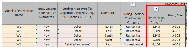
- Cross-check vertical fenestration products listed in Table 2 of the Proposed Envelope Assemblies tab with the design documents to confirm alignment. (The location of window schedules should be apparent from Plans/Specs reference included in this table.) Focus the review on fenestration products that account for the largest area.
- Refer to design document referenced in Plans / Specs column for the fenestration units being reviewed to confirm that specified U-factor, SHGC and VT align with the values reported in Table 2 of the Proposed Envelope Assemblies tab.
- Verify that the required supporting information specified to the right of Table 2 of the Proposed Envelope Assemblies tab is included in the submittal package.
- Review supporting documentation to verify that U-factor, SHGC and VLT are established correctly
using the approved method, as described below.
- 90.1 Section 5.8.2.1 requires that the performance of the windows and other fenestration products—including U-factor, SHGC, VT, and air leakage rate—be determined by a laboratory accredited by the National Fenestration Rating Council (NFRC) or another nationally recognized rating authority. Fenestration U-Factor must be determined in accordance with NFRC 100; SHGC and VT must be determined in accordance with NFRC 200. Other approaches, such as AMCA, are not allowed.
- Default values from 90.1 Appendix A (e.g., 90.1 Table A8.2 for the vertical fenestration) must be used for the fenestration products for which NFRC 100 and NFRC 200 test results are not available.
- 90.1 Section 5.8.2.2 requires that all manufactured and site-built fenestration and door products state the rated performance factors either on a label or a signed and dated manufacturer’s certificate provided with the product. If such information is not available, projects must use the defaults from 90.1 Table A8.1-1.
- The NFRC standards referenced in 90.1 Section 5.8.2.3 require that the rated U-value take into account properties of the entire fenestration assembly, including heat loss through the center of glass, edge of glass, sash, and frame elements. This requirement is often overlooked for custom fenestration, with center of glass properties used in lieu of the properties of the entire assembly, which typically underestimates fenestration U-value.
- Confirm that Visible Light Transmittance (VLT) is provided. VLT affects savings from daylighting controls. Fenestration with lower SHGC reduces space solar heat gains (with positive impact on cooling), but often have lower VLT which reduces daylighting.
BE16-B, BE16-P Modeled U-factor, SHGC and VLT of the baseline/budget and proposed fenestration are as reported in the Compliance Form
Review Tips
- Use simulation reports to verify that the modeled U-factor, SHGC and VLT are as reported in the
Compliance Form. The reported values are found at the following locations:
Baseline/budget design: Table 1 in the Envelope Areas tab.
Proposed Design: Table 2 in the Proposed Envelope Assemblies tab - Focus on fenestration types that account for the largest area.
BE17-B Baseline/budget infiltration rate reported in the Compliance Form is established correctly
90.1 2016 and 2019 ECB
Air-leakage is not prescribed. Thus, it must be modeled the same in the budget and proposed design Based on Table 11.5.1 No1.
90.1 2022 ECB
Table 12.5.1 No 5 Column B (f): The air leakage rate of the building envelope (I75Pa) at a pressure differential of 75 Pa (0.30 of water) shall be 0.35 cfm/ft2 of building envelope area and shall be converted to appropriate units for the simulation software using the same method as the proposed design.
90.1 2016 PRM
Table G3.1 Proposed Building Performance No 5 (b): The air leakage rate of the building envelope (I75Pa) at a fixed building pressure differential of 0.3 in. of water shall be 0.4 cfm/ft2. Infiltration must be modeled using the same methodology, air leakage rate and adjustments for weather and building operation in both the proposed design and the baseline building design. The air leakage rate of the building envelope must be converted to appropriate units for the simulation program using one of the methods in 90.1 Section G3.1.1.4.
90.1 2019 PRM
Table G3.1 Baseline Building Performance No 5(h): The air leakage rate of the building envelope (I75Pa) at a fixed building pressure differential of 0.3 in. of water shall be 1.0 cfm/ft2.The air leakage rate of the building envelope shall be converted to appropriate units for the simulation program using one of the methods in Section G3.1.1.4.
90.1 2022 PRM
G3.2 New Construction/Major AlterationsTable G3.1 Baseline Building Performance No 5(i): same as Table G3.1 Baseline Building Performance No 5(h) described above for the 90.1 2019 PRM.
G3.3 Minor Alterations
Section G3.3.2.5, which is applicable to alterations that do not meet the criteria in 90.1 G3.1.4a, requires that when Section 5.4.3.1.3 applies, the air leakage rate of the building envelope(I75Pa) shall be equal to 0.35 cfm/ft2 of building envelope area at a pressure differential of 75 Pa (0.30 in. of water). The air leakage rate shall be converted to appropriate units for the simulation software using the same method as the proposed design.
Review Tips – ECB
- 90.1 2016 and 2019: Infiltration rate is not prescribed thus any reasonable rate may be modeled. Modeling unrealistically high air leakage will exaggerate contribution of heating energy use toward budget building performance and may skew the compliance outcome. Assumptions that are substantially different from the default values shown in Table 1 of the Infiltration tab may be questioned if heating is one of the impactful end uses.
- 90.1 2022: The required infiltration rate at 75Pa pressure differential is automatically calculated in Table 1 of the Infiltration tab shows the applicable budget infiltration rate.
Review Tips – PRM
- The required infiltration rate at 75Pa pressure differential is automatically calculated in
Table 1 of the Infiltration tab shows the applicable baseline infiltration rate. Overrides
may be required for alterations subject to 90.1 2022 Section G3.3 which will be shown in
bold brown.
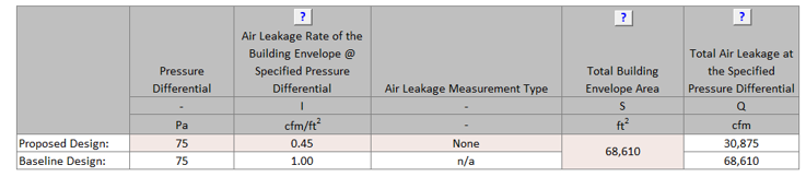
BE17-P Proposed infiltration rate reported in the Compliance Form is established correctly.
90.1 2016 and 2019 ECB
Air-leakage is not prescribed and thus must be modeled with the same rate as in the budget design.
90.1 2016 PRM
Table G3.1 No 5: The infiltration rate in the proposed design must be the same as in the baseline, except when whole-building air leakage testing in accordance with ASTM E779 is specified during design and completed after construction, the measured air leakage rate must be modeled in the proposed design.
90.1 2019 PRM
Table G3.1 Proposed Building Performance column No 5b: The air leakage rate of the building envelope (I75Pa) at a fixed building pressure differential of 0.3 in. of water shall be 0.6 cfm/ft2 for buildings providing verification in accordance with Section 5.9.1.2. The air leakage rate of the building envelope shall be converted to appropriate units for the simulation program using one of the methods in Section G3.1.1.4., except when whole-building air leakage testing in accordance with ASTM E779 is specified during design and completed after construction, the measured air leakage rate must be modeled in the proposed design.
90.1 2022 ECB/PRM
Table 12.5.1 No 5 Column A (b)/Table G3.1 Proposed Building Performance column No 5b: The air leakage rate of the building envelope shall be in accordance with one of the following:
- When whole-building pressurization testing is required or specified during design, and completed in accordance with Section 5.4.3.1.4, the measured air leakage rate of the building envelope (I75Pa) at a fixed building pressure differential of 75 Pa (0.30 in. of water) shall be modeled for purposes of demonstrating compliance with this standard.
- For buildings providing verification in accordance with Section 5.9.1.2, the air leakage rate of the building envelope (I75Pa) at a fixed building pressure differential of 75 Pa (0.30 in. of water) shall be 0.45 cfm/ft2.The air leakage rate of the building envelope shall be converted to appropriate units for the simulation program using one of the methods in Section 12.5.3.
Review Tips
- Table 1 of the Infiltration tab shows the applicable infiltration rate at 75Pa pressure differential for the proposed design assuming no air leakage testing was performed. If the air leakage rate for the proposed design is over-written by modeler, the entered values is show in light brown font.
- If the value is over-written, verify the following:
- Confirm that infiltration testing report is submitted.
- Confirm that test results are based on the approved testing method (e.g., ASTM E3158 for 90.1 2022 (see 90.1 Section 5.4.3.1.4 for other approved methods), E779 or E1827 for 90.1 2019, or E779 for 90.1 2016).
- Confirm that test results at 75Pa shown in the testing documentation are correctly transferred to Table 1 for the proposed design on the Infiltration tab in the Compliance Form.
BE18-B, BE18-P Baseline/budget and proposed modeled infiltration rate reflects the values reported in the Compliance Form
Review Tips
- Use the simulation reports to verify that the modeled baseline/budget infiltration rate is as reported in Table 2 of the Infiltration tab. Ensure that both the units (e.g., CFM/SF, ACH) and the value is correct.
- Common Mistakes
- An infiltration rate from Table 1 of the Infiltration tab is entered into simulation tool without converting to normal wind conditions. This exaggerates infiltration related loads by about factor of ten, significantly increasing the heating load and any savings from air leakage reduction in the proposed design.
BE19 Change in the proposed versus baseline/budget total annual and design loads from envelope components is reasonable given the difference in the proposed versus baseline/budget envelope parameters reported in the Compliance Form
Review Tips
-
This check verifies that the simulation outputs are generally consistent with the
baseline/budget and proposed envelope parameters. The check does not consider factors such as
thermal mass, exposure and shading, so look for a general correlation and not an exact match.
- If a given envelope component has the same or very similar thermal properties in the baseline (budget) and proposed design, heating and cooling losses and gains from this component should be the same or very similar based on the simulation outputs. For example, all 90.1 2016/2019 Energy Cost Budget projects and most 90.1 2016/2019 Performance Rating Method projects (except for those that performed air leakage testing) must model the same infiltration rate in the baseline/budget and proposed design, thus the heating and cooling losses and gains from infiltration are expected to be the same or very close in the baseline/budget and proposed simulations.
-
Conductive heat losses through surfaces (windows, exterior walls, roofs) should
correlate to the surface U-value and area.
Example 1: Based on the submittal, the proposed roof is U-0.032, compared to U-0.063 in the PRM baseline. The annual heat losses through the roof in the simulation output reports should be substantially lower in the proposed design. Assuming the skylight area is the same in the proposed and baseline building, the heat loss through the baseline roof should be about twice that of the proposed building roof (0.063/0.032=2).
Example 2: Based on the submittal, the proposed design has 40,000 SF of vertical fenestration with U-0.5; the baseline has 30,000 SF of fenestration with U-0. 5. The heat loss through windows due to conduction should go up. ((Uprop x Aprop)/(Ubase x Abase) = (40,000*0.5)/(30,000*0.5)~1.3
- Solar heat gains through windows should be approximately proportional to the product of the window area and SHGC.
The scope of this check depends on the reporting capabilities of the simulation tool.
BE20-B The baseline/budget building performance is an average of four orientations, if required
90.1 2016, and 2019/2022 ECB
Table 11.5.1 Column B #5 (c)/Table 12.5.1 Column B #5 (d): If the vertical fenestration area facing west or east of the proposed building exceeds the area limit set in 90.1 Section 5.5.4.5, then the energy cost budget shall be generated by simulating the budget building design with its actual orientation and again after rotating the entire budget building design 90, 180 and 270 degrees and then averaging the results.
90.1 2016, 2019, and 2022 PRM
Table G3.1 Baseline Building Design column #5 (a): The baseline building performance must be calculated by simulating the building with its actual orientation and again after rotating the entire building 90, 180 and 270 degrees, then averaging the results. The baseline building performance may be based on the actual building orientation (without averaging) if (a) the building vertical fenestration area on each orientation varies by less than 5%, or if (b) it is demonstrated to the satisfaction of the AHJ that the building orientation is dictated by site considerations, such as for major renovation projects, or building sharing party walls with the adjacent buildings on a city block.
Review Tips
- The Envelope Areas tab, “Baseline Orientation and Rotation” indicates whether the baseline/budget design was “rotated”. The default is auto-populated based on applying the appropriate 90.1 rules described above to the project. The modeler can over-write this default. If the default is over-written, confirm that an explanation is provided in the Note field and that it is acceptable. For example, the modeler may indicate that the project was not rotated because it is a major renovation.
- If it is established that the baseline must be rotated, verify that simulation results are reported for the four baseline orientations in the Compliance Calculations tab Table 2 (Baseline 0 Rotation, Baseline 90 Rotation, Baseline 180 Rotation, Baseline 270 Rotation).
BE20-P Proposed building orientation reflected in the Compliance Form is as specified
Review Tips
- Proposed building orientation must reflect the actual building exposure. Compare surface areas by orientation in Table 5 of the Envelope Areas tab to architectural drawings to ensure alignment in exposure.
BE21-B, BE21-P Baseline/budget and proposed building orientation is modeled as reported in the Compliance Form.
Review Tips
- Use the simulation reports listed below to verify that the modeled exposure is as reported in the Compliance Form.
BE22-P Proposed interior and exterior shading is established correctly in the Compliance Form
90.1 2016 and 2019/2022 ECB
Table 11.5.1 #5, Proposed Building Design column Exception 4/ Table 12.5.1 #5, Proposed Building Design column Exception 6Manually operated fenestration shading devices, such as blinds or shades, must not be modeled. Permanent shading devices, such as fins, overhangs, and light shelves, must be modeled.
90.1 2016 and 2019/ 2022 PRM
Table G3.1 Proposed Building Performance Column No 5 (a #4,5)/Table G3.1 Proposed Building Performance Column No 5 (a #6,7)- Manual fenestration shading devices, such as blinds or shades, must be modeled or not modeled the same as in the baseline building design.
- Automatically controlled fenestration shades or blinds must be modeled.
- Permanent shading devices, such as fins, overhangs, and light shelves must be modeled.
- Automatically controlled dynamic glazing may be modeled. Manually controlled dynamic glazing must use the average of the minimum and maximum SHGC and VT.
- All elements whose effective height is greater than their distance from a proposed building and whose width facing the proposed building is greater than one-third that of the proposed building shall be accounted for in the analysis.
- A site plan showing all adjacent buildings and topography that may shade the proposed building (with estimated height or number of stories).
90.1 2019 PRM
Table G3.1 Proposed Building Performance column No 5b: The air leakage rate of the building envelope (I75Pa) at a fixed building pressure differential of 0.3 in. of water shall be 0.6 cfm/ft2 for buildings providing verification in accordance with Section 5.9.1.2. The air leakage rate of the building envelope shall be converted to appropriate units for the simulation program using one of the methods in Section G3.1.1.4., except when whole-building air leakage testing in accordance with ASTM E779 is specified during design and completed after construction, the measured air leakage rate must be modeled in the proposed design.
Review Tips
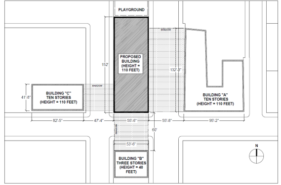
-
For PRM projects, review the site plan showing all adjacent buildings and topography that may
shade the proposed building with the estimated height or number of stories. An example of site
shading documentation is provided below.
- Exterior and interior shading of the proposed design is described in the Envelope Areas tab Table 8. The applicable 90.1 modeling rules are shown in the table and may be over-written by the modeler. The over-written values are shown in brown font. If any of the values are overwritten, the changes must be described in the notes below the table. Confirm that modeling approach aligns with 90.1 rules stated above.
- The check should be performed on projects located in Climate Zones 0-5.
BE22-B Baseline/Budget interior and exterior shading is established correctly in the Compliance Form
90.1 2016 and 2019/2022 ECB
Table 11.5.1 Column B #5 (c)/Table 12.5.1 Column B #5 (d)No shading projections are to be modeled; fenestration is assumed to be flush with the wall or roof.
90.1 2016 and 2019/2022 PRM
G3.2 New Construction/Major AlterationsTable G3.1 Baseline Building Performance column #5 (d)/Table G3.1 Baseline Building Performance column #5 (f)
- All vertical fenestration shall be assumed to be flush with the exterior wall, and no shading projections shall be modeled.
- Manual window shading devices such as blinds or shades are not required to be modeled.
Shading by adjacent structures and terrain must be the same as in the proposed design.
G3.3 Minor AlterationsAlterations subject to 90.1 2022 Section G3.3 (i.e., Minor Alterations) should model interior and exterior shading identically in the baseline and proposed models since there are no relevant requirements in Section 5 applicable to alterations.
Review Tips
- Exterior and interior shading of the proposed design is described in the Envelope Areas tab Table 8. The applicable 90.1 modeling rules are shown in the table and may be over-written by the modeler. The over-written values are shown in brown font. If any of the values are overwritten, the changes must be described in the notes below the table. Confirm that modeling approach aligns with 90.1 rules stated above.
- Shading is especially important in climate zones where cooling is significant, such as Climate Zones 0-5, and where fenestration area is relatively large.
BE23-B, BE23-P Baseline/Budget and proposed interior shading is modeled as reported in the Compliance Form
Review Tips
- Review simulation reports to confirm that interior and exterior shading is modeled as reported in the Compliance Form.
- The check should be performed on projects located in Climate Zones 0-5.
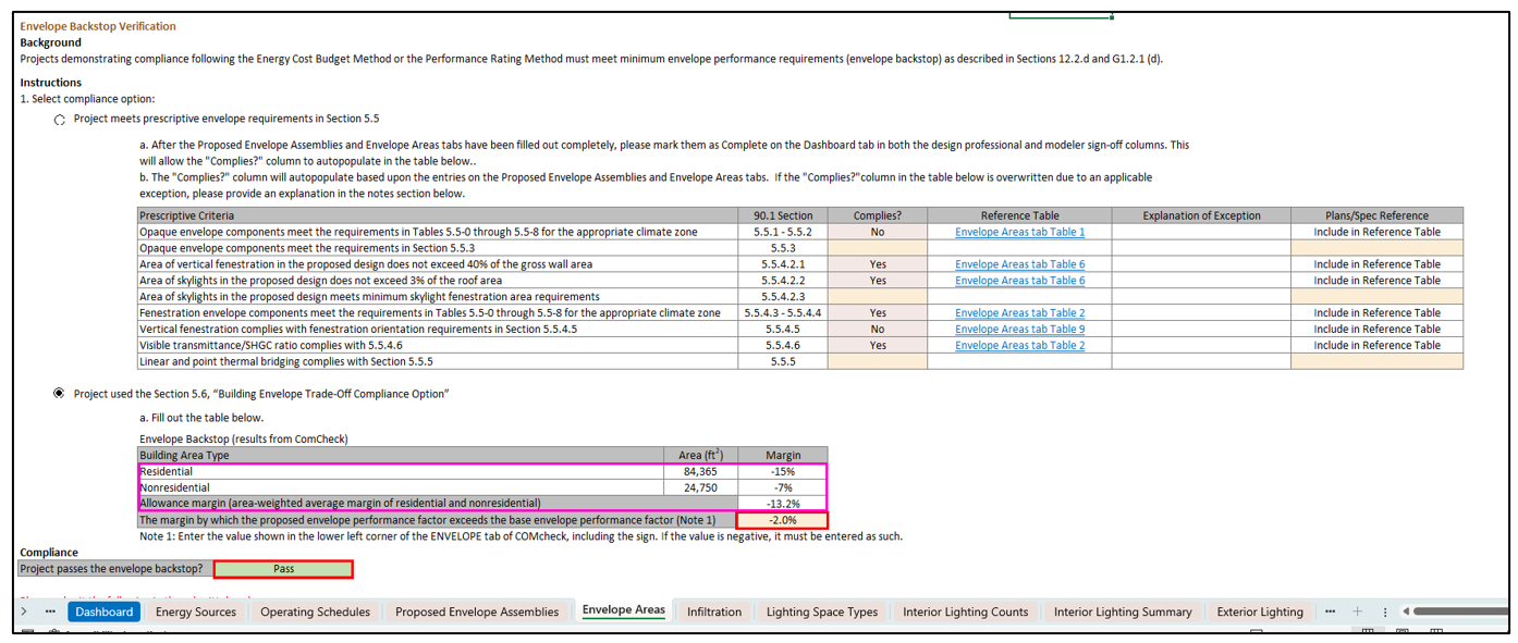
BE24-P, Proposed envelope complies with minimum mandatory envelope requirements
90.1 2016 and 2019 ECB and PRM
No minimum mandatory envelope requirements other than those included in 90.1 Section 5.4.
90.1 2022 ECB/PRM
12.2d/G1.2.1dFor new buildings, one of the following must be met:
- The building envelope complies with Section 5.5, “Prescriptive Building Envelope Compliance Path.”
- Using Section 5.6, “Building Envelope Trade-Off Compliance Option,” the proposed envelope performance factor shall not exceed the base envelope performance factor by more than 15% in multi-family residential, hotel/motel, and dormitory building area types. For all other building area types, the limit shall be 7%. For buildings with both residential and nonresidential occupancies, the limit shall be based on the area-weighted average of the gross conditioned floor area.
Review Tips
-
This review check applies to 90.1 2022 projects only, inputs for documenting compliance with
Sections 12.2d/G1.2.1d are included in the “Envelope Backstop Verification” section on the
Envelope Areas tab in the Compliance Form (a screenshot from the section is shown below for
reference).
Review the section to check that one of the compliance options is selected. If compliance with Section 5.5, “Prescriptive Building Envelope Compliance Path” is selected then ensure that “Yes” is selected for each row in the “Complies?” column in the table shown below. Some of the rows autopopulate with manual overrides shown in bold orange. If “Exception Applies” is selected review the explanation for validity. For peach cells that require a user input, manual overrides, or scenarios in which exceptions apply, ensure that the inputs and explanations align with the documentation noted in the “Plans/Spec Reference” column.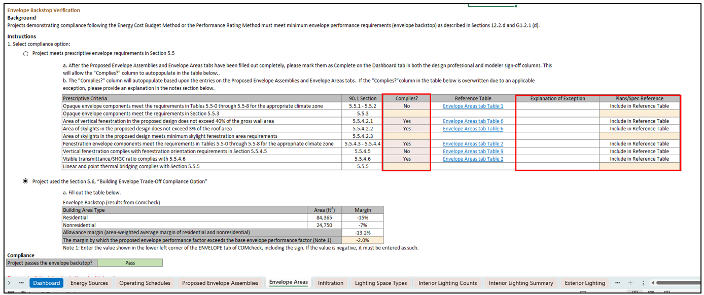
For projects following the Section 5.6, “Building Envelope Trade-Off Compliance Option” the 90.1 Sections 12.2d/G1.2.1d allowances are such that the proposed envelope performance factor cannot exceed the base envelope performance factor by more than 15% for multifamily/residential, hotel/motel, and dormitory building area types and for all other building area types, the limit is set at 7%. For buildings with both residential and nonresidential occupancies, the limit is determined based on the area-weighted average of the gross conditioned floor area. The allowance margin is automatically calculated in the Compliance Form on the Envelope Areas tab, as shown below outlined in pink, based on 90.1 Sections 12.2d/G1.2.1d allowances and the building area types entered on the General Information tab in Table 1.If the Section 5.6, “Building Envelope Trade-Off Compliance Option” option is selected, then compare the margin by which the proposed envelope performance factor exceeds the base envelope performance factor entry with the provided Comcheck report requested in Submittal Checklist #36 to ensure they match. Confirm that the field shown below reports a “Pass” outcome. See fields outlined in red in the graphic below from the Envelope Areas tab in the Compliance Form.