Airside HVAC (AHVAC)
Overview
This group of checks covers air-side systems including type, heating and cooling efficiency and controls. In addition, it covers fan systems and controls, mechanical ventilation including ventilation rate, controls and exhaust air energy recovery, and economizer. Table 12 summarizes the checks included in this group.
Table 12: Air-side HVAC Quality Control Checks Overview
AHVAC01–P Thermal blocks are established correctly
90.1 2019/2022 ECB, 90.1 2016 and 2019/2022 PRM
11.7.2 g/12.7.2 g, G1.3.2 i/ G1.3.2 j: A diagram showing the thermal blocks used in the computer simulation must be submitted.
90.1 2016 and 2019/2022 ECB, 90.1 2016, 2019, and 2022 PRM
90.1 Table 11.5.1 #7/12.5.1 #7, 90.1 G3.1 #7Thermal blocks must be based on the HVAC zones specified in the proposed design. Where HVAC zones are defined on drawings, each HVAC zone must be modeled as a separate thermal block. Different HVAC zones may be combined into a single thermal block if all of the following applies:
- Zones have similar occupancy types (e.g., include primarily office spaces)
- Have windows facing the same orientation, or their orientations vary by less than 45 degrees
- Are served by the same kind of HVAC system
Thermal blocks in the baseline (budget) design must be the same as in the proposed design.
90.1 Table 11.5.1 #8/12.5.1 #8 and Table G3.1 #8: Special rules apply to projects with no HVAC zones designed. Thermal blocks in the baseline (budget) design must be the same as in the proposed design.
90.1 Table 11.5.1 #9/12.5.1 #9 and Table G3.1 #9
Residential occupancies such as multifamily must be modeled using at least one thermal block per
dwelling unit, except units facing the same orientations may be combined into one thermal block.
Corner units and units with roof or floor loads may only be combined with units sharing the same
features. Thermal blocks in the baseline (budget) design must be the same as in the proposed
design.
Review Tips
-
The submittal package for projects following the PRM or 2019 and 2022 ECB must include a diagram
showing the thermal blocks used in the computer simulation. Refer to the Review Checklist tab
#15 to identify the name of the file or document with the necessary information. The diagram
should include the labels corresponding to the block names used in the simulation, or a
description of the thermal block naming convention used. For example, the names of the thermal
blocks may be based on the space names shown on architectural drawings. Request thermal block
diagram if it is not included in the submittal package or lacks the necessary details. Even
though it is not required for projects following 90.1 2016 ECB, a reviewer may still choose to
request it to help verify that the relevant requirements of 90.1 are met.
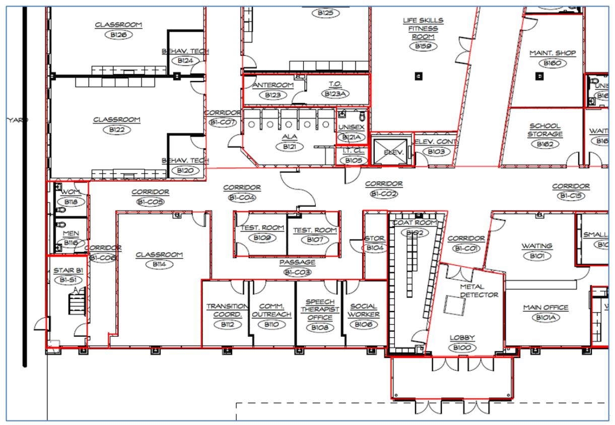
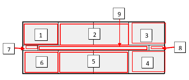
Figure 7: Sample Thermal Blocks Used in the Computer Simulation:
- The thermal blocks are summarized in Table 2 of the Interior Lighting Summary tab. Spot-check the table to confirm alignment with the submitted diagram.
-
The relevant 90.1 rules set the minimum level of details to which the project’s floor plans must
be captured in the model. HVAC zone may include one or more spaces where indoor conditions
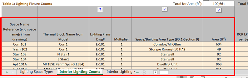
(e.g., temperature) are maintained by a single sensor (e.g., thermostat). Refer to Table 1 of
the Interior Lighting Counts tab where detailed information for thermal blocks is provided. Spot
check a sample of larger or typical thermal blocks with the submitted block diagram and
mechanical plans drawings to confirm that the rules we correctly applied to the project.
Example: A ten-story multifamily building with eight apartments, a corridor, and stairwells on each floor would be modeled with 27 thermal blocks (highlighted in red in the figure below), including nine thermal blocks on the top and bottom floors and another 9 thermal blocks on a typical middle floor to which a multiplier of 8 is applied to indicate that there are eight such floors in the building.
AHVAC02-B,P Thermal blocks are modeled as reported in the Compliance Form
Review Tips
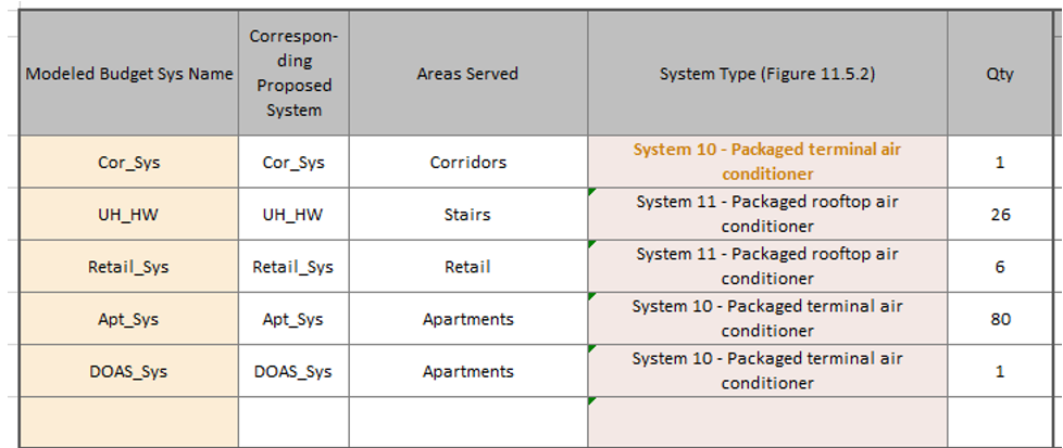
- Spot-check simulation reports to verify that the modeled thermal blocks for the baseline/budget and proposed design reflect thermal blocks reported in Table 2 of the Interior Lighting Summary tab.
AHVAC03–P All specified air-side HVAC systems are reported in the Compliance Form
Review Tips
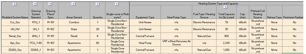
- Each HVAC system shown on mechanical schedules must be included in the Compliance Form. Cross-check information provided in Table 1a of the Proposed HVAC with the Mechanical Schedules to confirm that all specified air-side systems are reported.
- Common Mistakes
- Supplemental systems such as electric resistance unit heaters and baseboards that are often specified for mechanical rooms, stairwells and bathrooms not reported in the Compliance Form.
AHVAC03–B Baseline/budget system types reported in the Compliance Form are established correctly
90.1 2016 and 2019/2022 ECB
Each HVAC system specified in the proposed design must have a corresponding baseline system established following 90.1 Figure 11.5.2/Figure 12.5.2, Table 11.5.2-1/Table 12.5.2-1 and accompanying notes.
90.1 2016 and 2019 PRM
Baseline HVAC system type and description must be based on 90.1 Section G3.1.1. Mixed use buildings that include both residential and non-residential building types with non-predominant conditions accounting for more than 20,000 ft2 of conditioned floor area must have a separate baseline system type established for each set of conditions. The following baseline systems apply to climate zones 3B, 3C, and 4 to 8:
- All residential occupancies (dormitory, hotel, motel and multifamily):
System 1 – PTAC
- All public assembly occupancies (houses of worship, auditoriums, movie theaters, performance theaters,
concert halls, arenas, enclosed stadiums, ice rinks, gymnasiums, convention centers, exhibition centers
and auditoriums):
System 3—PSZ-AC if <120,000 ft2
System 12—SZ-CV-HW if >= 120,000 ft2
- Heated-only storage (e.g. warehouse) meeting the definition of non-predominant conditions, or
certain heated-only spaces such as storage rooms, stairwells, electrical/mechanical rooms
(90.1 Section G3.1.1 e):
System 9—Heating and ventilation
- All other non-residential:
System 3—PSZ-AC if 3 floors or fewer and <25,000 ft2
System 5—Packaged VAV with reheat if 4 or 5 floors and <25,000 ft2 or 5 floors or fewer and 25,000 ft2 to 150,000 ft2
System 7—VAV with reheat if more than 5 floors or >150,000 ft2
The following baseline systems apply to climate zones 0 to 3A:
- All residential occupancies (dormitory, hotel, motel and multifamily):
System 1 – PTHP
- All public assembly occupancies (houses of worship, auditoriums, movie theaters, performance
theaters, concert halls, arenas, enclosed stadiums, ice rinks, gymnasiums, convention centers,
exhibition centers and auditoriums):
System 4—PSZ-HP if <120,000 ft2
System 13—SZ-CV-ER if >= 120,000 ft2
- Heated-only storage (e.g. warehouse) meeting the definition of non-predominant conditions, or
certain heated-only spaces such as storage rooms, stairwells, electrical/mechanical rooms
(90.1 Section G3.1.1 e):
System 10—Heating and ventilation
- All other non-residential:
System 4—PSZ-HP if 3 floors or fewer and <25,000 ft2
System 6—Packaged VAV with PFP boxes if 4 or 5 floors and <25,000 ft2 or 5 floors or fewer and 25,000 ft2 to 150,000 ft2
System 8—VAV with PFP boxes if more than 5 floors or >150,000 ft2
90.1 2022 PRM
G3.2 New Construction/Major AlterationsBaseline HVAC system type and description for projects following Section G3.2 must be based on 90.1 Section G3.2.1. Below is a summary of the process for determining the baseline HVAC system(s):
- Determine the combined gross conditioned and semi-heated floor area for each of the following building
area
types in the proposed design:
- Residential and residential-associated zones
- Residential associated HVAC zone (90.1 Section 3): Any HVAC zone that primarily includes nonresidential spaces designed to serve occupants of residential spaces, including but not limited to corridors, stairwells, elevator lobbies, and common restrooms, on a floor where over 75% of the gross conditioned floor area are residential spaces. This definition does not apply to HVAC zones within hospitals.
- Public assembly
- Heating-only storage
- Retail
- Hospitals
- Other nonresidential
- Classify the nonresidential building area type with the largest combined area as the predominant nonresidential building area type. Add the combined area of any remaining nonresidential building area types with less than 20,000 ft2 to the combined area of the predominant nonresidential building area type.
- Select a baseline HVAC system type from Table G3.1.1-3 for each of the following building area
types included in the proposed design:
- Residential based on Section G3.2.1.1(a)
- Predominant nonresidential based on Section G3.2.1.1(b)
- Each additional nonresidential building area type with more than 20,000 ft2 of combined area based on Section G3.2.1.1(a)
G3.3 Minor Alterations
The systems and equipment included in the scope of retrofit for alterations subject to 90.1 2022 Section G3.3 (i.e.,
Minor Alterations) must be modeled following the requirements of G3.3.2.8(a) which specify that the
baseline HVAC system type is the same as the proposed design. Exception: if the proposed
design includes variable refrigerant flow heat pumps or single-zone systems with electric resistance heat,
then air source heat pumps shall be modeled in the baseline design.
Review Tips – 90.1 ECB
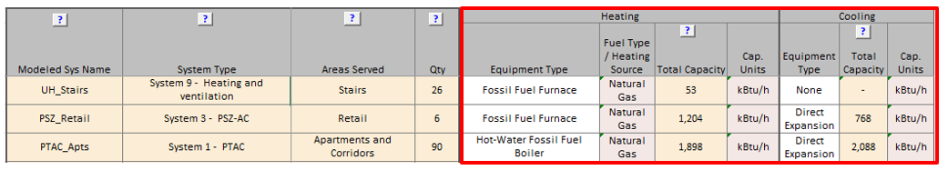
- Budget HVAC system types are reported in Table 1a of the Budget HVAC ECB tab. Since ECB requires
that each system in the proposed design has a corresponding budget system, the default budget system
types are set in the table by applying the appropriate rules of ECB to each proposed system. The over-written
defaults are shown in brown bold font and should be verified.
Review Tips – 90.1 PRM
- Baseline HVAC system types are reported in Table 1a of the Baseline HVAC PRM tab. Spot-check to confirm that
the baseline systems were established correctly based on the applicable 90.1 rules. Refer to 90.1 2022 Section G3.3 Performance Calculations for Other Alterations for
review tips for alterations subject to 90.1 2022 Section
G3.3 (i.e., Minor alterations).

- Common Mistakes (not applicable to alterations subject to 90.1 2022 Section G3.3)
- Baseline HVAC heating fuel source based on the heating source used in the proposed design instead of based on the project’s climate zone. For example, a project in climate zone 4A that has electric heating in the proposed design should not have electric heating modeled in the baseline design.
- Modeling dedicated outdoor air system (DOAS) in the baseline on projects with DOAS in the proposed design. Instead, heating, cooling and ventilation in the baseline design is provided by systems determined following 90.1 Section G3.1.1/G3.2.1.
- System 5 - 8 are not modeled as System per floor; instead, multiple systems per floor are modeled to maintain the same arrangement as in the proposed design. This impacts a baseline system’s individual OA to supply ratio which determines baseline energy recovery requirements and may also affect the baseline system efficiency.
AHVAC04–B,P All baseline/budget and proposed air-side HVAC systems reported in the Compliance Form are modeled.
Review Tips
- Spot-check simulation reports to confirm that all proposed air-side systems reported on Table 1a of the Proposed HVAC tab are modeled and reflect the reported system type and fuel.
- Spot-check simulation reports to confirm that all budget/baseline air-side HVAC systems reported in Table 1a of the Budget HVAC ECB/ Baseline HVAC PRM tabs are modeled and reflect the reported system type and fuel. For alterations subject to 90.1 2022 Section G3.3 (i.e., Minor Alterations) review Table 1a on the Proposed HVAC tab for baseline systems since there should be a one-to-one relationship between the baseline and proposed.
- Confirm alignment between heating/cooling fuel sources reported in the Compliance Form for baseline/budget and proposed design with modeling results. For example, if some systems reported in the Compliance Form use electric resistance heat, simulation output reports must show electricity consumption under space heating end use.
- Common Mistakes
- Using incorrect “template” within the simulation tool to model specified system type, such as a constant volume system template to model a variable volume system.
- Omitting electric resistance space heaters and radiators from the model
The following system types are commonly used to model PRM Baseline systems:
System 1 – PTAC, PSZ-AC, PVVT-AC
System 3 – PSZ – AC, PVVT-AC
System 5 – PVAVS, PIU
System 7 – VAVS, PIU
System 9 – UHT
Output Data: “Monthly Simulation Results” report for an Air System
AHVAC05–P Heating and cooling types and capacities of the proposed air-side HVAC systems reported in the Compliance Form reflect Design Documents.
Review Tips
-
Heating and cooling types and capacities of the air-side HVAC systems are reported in Table 1a of
the Proposed HVAC tab. Cross-check the provided information with the design documents for a sample
of systems to confirm alignment.
AHVAC05–B Heating and cooling types and capacities of the baseline/budget air-side HVAC systems reported in the Compliance Form are established correctly
90.1 2016 and 2019/2022 ECB
The equipment capacities for the budget building design must be sized proportionally to the capacities in the proposed design based on sizing runs, i.e., the ratio between the capacities used in the annual simulations and the capacities determined by the sizing runs must be the same for both the proposed design and budget building design (90.1 Section 11.5.2 i/90.1 Section 12.5.2 i). The capacity of each system in the budget building should have a reasonable correlation to the corresponding system in the proposed design. For example, if the proposed design has a less efficient envelope compared to the budget design, budget system capacities are expected to be lower compared to the corresponding proposed system.
90.1 2016 PRM
G3.1.2.2 Equipment Capacities: The coil capacities for the baseline systems must be based on sizing runs for each orientation (90.1 Table G3.1, No. 5 a) and oversized by 15% for cooling and 25% for heating; i.e., the ratio between the cooling/heating capacities used in the annual simulations and the capacities determined by the sizing runs must be 1.15/1.25. Weather conditions used in sizing runs must be based either on hourly historical weather files with typical peak conditions, or 99.6% heating design temperatures and 1% dry-bulb and 1% wet-bulb cooling design temperatures from 90.1 Appendix D, as illustrated below.

Figure 41: Example Design Conditions from 90.1 Appendix D
90.1 2019 PRM
G3.1.2.2 Equipment Capacities: The coil capacities for the baseline systems must be based on sizing runs for each orientation (90.1 Table G3.1, No. 5 a) and oversized by 15% for cooling and 25% for heating; i.e., the ratio between the cooling/heating capacities used in the annual simulations and the capacities determined by the sizing runs must be 1.15/1.25.
Weather conditions used in sizing runs to determine baseline equipment capacities is required to be based on design days developed using heating design temperatures, cooling design temperature, and cooling design wet-bulb temperature. For cooling sizing runs, schedules for internal loads, including those used for infiltration, occupants, lighting, gas and electricity using equipment, are required to be equal to the highest hourly value used in the annual simulation runs and applied to the entire design day. For heating sizing runs, schedules for internal loads, including those used for occupants, lighting, gas and electricity using equipment, are required to be equal to the lowest hourly value used in the annual simulation runs, and schedules for infiltration are required to be equal to the highest hourly value used in the annual simulation runs and applied to the entire design day. An exception is that for cooling sizing runs in residential dwelling units, the infiltration, occupants, lighting, gas and electricity using equipment hourly schedule are required to be the same as the most used hourly weekday schedule from the annual simulation.
90.1 2022 PRM
G3.2 New Construction/Major AlterationsG3.2.2.2 Equipment Capacities: Requirements are the same as described for the 90.1 2019 PRM above.
G3.3 Minor Alterations
For the systems and equipment included in the scope of retrofit for alterations subject to 90.1
2022 Section G3.3 capacities for the baseline design are required to be sized proportionally to
the capacities in the proposed design based on sizing runs—i.e., the ratio between the
capacities used in the annual simulations and the capacities determined by the sizing runs shall
be the same for both the proposed design and baseline building design based on 90.1 G3.3.2.8e.
Review Tips – ECB
- Heating and cooling types and capacities of the baseline air-side HVAC systems are reported in Table 1a of the Budget HVAC ECB tab of the Compliance Form.
- The capacity of each system in the budget building should have a reasonable correlation to the corresponding system in the proposed design. For example, if the proposed design has a less efficient envelope compared to the budget design, the budget system capacities are expected to be lower compared to the corresponding proposed system.
Review Tips – PRM
-
Heating and cooling types and capacities of the baseline air-side HVAC systems are reported
in Table 1a of the Baseline HVAC PRM tab of the Compliance Form. Refer to
90.1 2022 Section G3.3 Performance Calculations for Other Alterations
for review tips for alterations subject to 90.1 2022 Section G3.3 (i.e., Minor alterations).
- Heating and cooling types are shown in the Equipment Type columns and are auto-populated based on user selection in System Type column.
- The values entered in the Total Capacity columns for heating and cooling must be based on the simulation results
-
The cooling capacity inputs should be compared to the typical shown in Table 13. Projects with
lower SF/Ton should be flagged as they may have an overly lenient (less efficient than required)
baseline. Exaggerated baseline cooling system capacity may lead to the system operating at low
fraction of design capacity for most of the year, lowering the annual average efficiency. For
projects with constant volume systems in the baseline, this will also exaggerate the baseline
fan energy use. In addition, if a project uses a utility rate structures with demand charges,
this will exaggerate the baseline demand charges and energy cost.
The issue may be caused by one or more of the following:
- Design conditions are not entered correctly
- Higher than typical internal gains from lighting, occupancy or miscellaneous equipment during design day
- Lower than typical modeled design cooling temperature
- Cooling is oversized by more than 15% to reduce number of hours for which cooling load is not met in the simulation. However, the unmet load hours are often due to simulation mistakes and should be addressed in lieu of increasing cooling capacity. For example, cooling schedule may allow temperatures to go up significantly during unoccupied hours resulting in higher-than-expected load when the building switches to occupied mode.
Table 13: Cooling Capacity Rule of Thumb*
*From ASHRAE Pocket Guide for Heating, Ventilation, Refrigeration (I-P Edtion), 7th Edition
(see latest edition
here)
| Occupancy Type | Cooling Load, SF/Ton 1 Ton = 12,000 Btu/hr = 12 MBH |
|---|---|
| Apartment high-rise | 400 - 450 |
| Public assembly | 250 - 400 |
| Schools – universities | 185 - 240 |
| Hotels, motels, dormitories | 300 - 350 |
| Office buildings | 280 - 360 |
AHVAC06–B,P Heating and cooling capacities of the air-side HVAC systems are modeled as reported in the Compliance Form
Review Tips
- Spot-check simulation reports to verify that modeled heating and cooling capacities for a sample of air-side HVAC systems reflect values reported in the Compliance Form. (See Table 1a of the Proposed HVAC tab for reported capacities of the proposed systems; see Table 1a of the Budget HVAC ECB/ Baseline HVAC PRM tabs for budget/baseline system capacities that must be modeled. For alterations subject to 90.1 2022 Section G3.3 (i.e., Minor Alterations), if baseline capacities were requested under AHVAC05-B, compare the documentation provided to simulation reports.
- For PRM baseline systems (excluding alterations subject to 90.1 2022 Section G3.3), use simulation input and output reports to verify that the ratio of the baseline system capacity to the simulated peak load is approximately 15% for cooling and 25% for heating. The oversizing may be higher due to the difference in internal gain and weather used for equipment sizing versus the annual simulation. Oversizing significantly higher than 15% should be flagged.
- For ECB budget systems and PRM alterations subject to 90.1 2022 Section G3.3 (i.e., Minor Alterations):
- Use simulation input and output reports to confirm that the ratio of equipment heating/cooling capacity to the simulated heating/cooling peak load should be the same or very similar for the budget systems as for the corresponding systems in the proposed design, based on the simulation output reports.
- Calculate the effective heating/cooling full load hours (EFLH) as the ratio of the annual heating/cooling load to the heating/cooling equipment capacity. The effective heating/cooling EFLH should be similar between the proposed systems and the respective budget systems.
- Common Mistakes:
- Having the software auto-size the proposed systems instead of using heating and cooling capacities specified on mechanical schedules.
AHVAC07–P Reported air-side HVAC systems cooling and heating efficiencies reflect design documents.
Review Tips
- Heating and cooling types and capacities of the air-side HVAC systems are reported in Table 1a of the Proposed HVAC tab. Cross-check the provided information with the design documents for a sample of systems to confirm alignment.
-
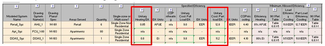
90.1 Section 6 includes tables with the minimum efficiency requirements for different types of
HVAC systems. These requirements are mandatory and must be met by all specified systems. The
requirements applicable to each specified system are shown in Table 1a. Efficiencies that are
below the required minimum are highlighted in red and must be noted in the review comments.
AHVAC08–P Cooling and heating efficiencies of the specified air-side HVAC systems meet the mandatory minimums in 90.1 Section 6
Review Tips
-
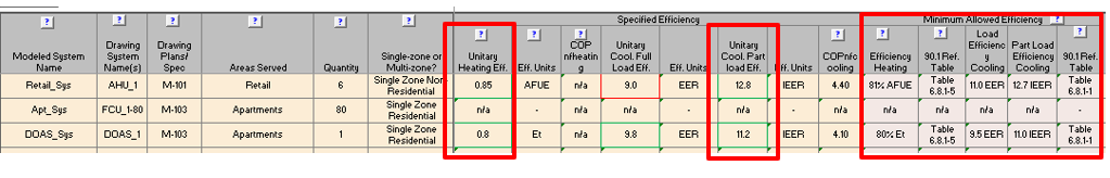
90.1 Section 6 includes tables with the minimum efficiency requirements for different types of
HVAC systems. These requirements are mandatory and must be met by all specified systems. The
requirements applicable to each specified system are shown in Table 1a of the Proposed HVAC tab.
Efficiencies that are below the required minimum are highlighted in red and should be flagged.
Spot check the validity of manual overrides of the minimum allowed efficiency values which would
be shown in brown bold font. Existing systems and components not in the scope of the project do
not need to comply with minimum efficiency requirements.
AHVAC08–B Baseline/budget air-side systems’ heating and cooling efficiencies reported in the Compliance Form are established correctly
90.1 2016 and 2019/2022 ECB
All HVAC equipment in the budget building design must be modeled at the minimum part load and full load efficiencies in 90.1 Sections 6.4.
90.1 2016 and 2019 PRM
Baseline system efficiencies must be based on 90.1 Tables G3.5.1 through G3.5.6.
90.1 2022 PRM
G3.2 New Construction/Major AlterationsRequirements are the same as for the 90.1 2016 and 2019 PRM above.
G3.3 Minor Alterations
Systems and equipment included in the scope of retrofit for alterations subject to 90.1 2022
Section G3.3 (i.e., Minor Alterations) are required to be modeled at the minimum part load and
full load efficiencies in 90.1 Section 6.4.1 in the baseline design model. All other baseline
systems and equipment shall be modeled the same as in the proposed design.
Review Tips – 90.1 ECB
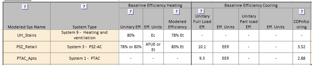
- Heating and cooling system efficiencies are reported in Table 1a of the Budget HVAC ECB tab.
The defaults are based on the efficiency tables referenced in “90.1 Ref Table” column. Any
over-written defaults which are shown in brown font should be confirmed by the reviewer.
Review Tips – 90.1 PRM
-
Refer to
90.1 2022 Section
G3.3 Performance Calculations for Other Alterations
or review tips for alterations subject to 90.1 2022 Section G3.3 (i.e., Minor alterations).
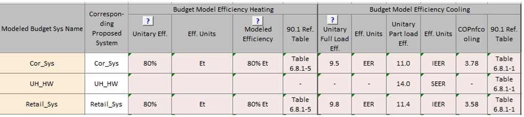
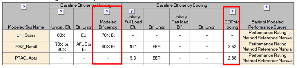
Heating and cooling system efficiencies are reported in Table 1a of the Baseline HVAC PRM
tab and are auto-populated based on user inputs in the System Type column and the Total
Capacity columns for heating and cooling. In addition, the appropriate simulation inputs for
heating and cooling efficiency are automatically established and shown in the Modeled
Efficiency and COPnfcooling columns. The calculations reflect 90.1 requirements for
extracting fan power from efficiency rating.
AHVAC09–P Modeling inputs for the proposed heating and cooling efficiency are provided in the Compliance Form and established correctly
90.1 2016 and 2019/2022 ECB and PRM
90.1 Section 11.5.2/12.5.2, Table G3.1 #10The modeled efficiency of the proposed systems must be adjusted to remove the supply fan energy corresponding to the conditions at which the unit was tested by the manufacturer. This requirement applies to all systems with a cooling efficiency rating expressed as EER and SEER. The cooling efficiency with the fan energy excluded is referred to as COPnfcooling must be calculated based on manufacturer data at AHRI Rating Conditions, as follows (see also the 90.1 User's Manual):
Indoor Fan Power [W] = (Gross Cooling [Btu/h]-Net Cooling [Btu/h])/3.413[Btu/h x W]
COPnfheating = Gross Heating [Btu/h]/(Total Input Power [W] - Indoor Fan Power [W]) x 3.413 [Btu/hx W])
Review Tips
- COPnfcooling and COPnfheating for each proposed HVAC system with DX heating or cooling is included in Table 1a of the Proposed HVAC tab. Confirm that it is calculated as appropriate for a sample of HVAC systems and comment if incorrect. Focus the review on DX systems with the highest heating/cooling capacities and spot-check the rest.
-
Example: The specified air-handling unit has the following rated performance based on the manufacturer’s catalog:
Gross Cooling Capacity – Full Load [Btu/hr] 103,000 EER / IEER 12.6 / 22.5 AHRI Net Cooling Capacity – Full Load [Btu/hr] 99,000 System Power [kW] 7.86
Indoor Fan Power [W]= (Gross Cooling [Btu/h] – Net Cooling [Btu/h])/3.413 [Btu/h x W]= (103,000-99,000)/3.412=1,172 [W]COPnfcool = Gross Cooling [Btu/h] / ((System Power [W] – Indoor Fan Power[W])*3.412[Btu/h x W] = 103,000/((7,860 – 1,172)*3.412)=0.2214
AHVAC09–B Modeling inputs for the baseline/budget heating and cooling efficiency are provided in the Compliance Form and established correctly
90.1 2016 and 2019/2022 ECB
Section 11.5.2 c/12.5.2 c: For Systems 3,4,6,8,9,10,11, supply fan energy at AHRI test conditions must be extracted from efficiency rating using the provided methodology.
90.1 2016 PRM
The efficiency values included in 90.1 Tables G3.5.1 through G3.5.6 do not include supply fan energy so no adjustments are required.
90.1 2019 PRM
Section G3.1.2.1: For Systems 1 – 6, supply fan energy at AHRI test conditions must be extracted from efficiency rating using the provided methodology.
90.1 2022 PRM
G3.2 New Construction/Major AlterationsRequirements are the same as for the 90.1 2019 PRM above.
G3.3 Minor Alterations
Systems and equipment included in the scope of the retrofit for alterations subject to 90.1 2022
Section G3.3 (i.e., Minor Alterations) are required to be modeled such that supply fan energy is
extracted from the efficiency rating (where the efficiency rating includes supply fan energy) in
accordance with 90.1 Section 12.5.2c.
Review Tips
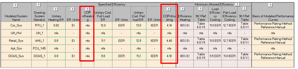
- The appropriate simulation inputs for heating and cooling efficiency are automatically established and shown in the Modeled Efficiency and COPnfcooling columns in Table 1a of the Baseline HVAC PRM or Budget HVAC ECB tabs (for alterations subject to 90.1 2022 Section G3.3 (i.e., Minor Alterations) see supplementary documentation, request this if not provided), depending on the compliance path. The calculations reflect 90.1 requirements for extracting fan power from efficiency ratings. For ECB projects, the defaults may be over-written by the modeler. The custom values may be verified.
AHVAC10-P The heating & cooling performance curves used in the proposed design simulation are based on an approved source
Review Tips
-
The modeled performance curves reflect variations in efficiency and capacity of the specified
equipment at the range of operating conditions. The basis of the modeled performance curves must
be specified in Table 1a of the Proposed HVAC tab.
The performance curves may be available from equipment manufacturers or developed based on the performance data provided by the manufacturer. If the performance curves for the specified equipment are not available, the default curves from the ANSI/ASHRAE/IES Standard 90.1-2016 Performance Rating Method Reference Manual (or latest available version) may be used.
- When custom performance curves based on manufacturer data are used for any of the systems, supporting documentation must be provided. Refer to Submittal Checklist tab #22 to confirm that it is included in the submittal. The provided calculations may be reviewed for a sample of performance curves. Alternatively, reviewer may verify that, based on the simulation reports, the realized annual average efficiency is similar to the rated IEER of the unit.
AHVAC10-B The heating & cooling performance curves used in the baseline/budget design simulation are based on an approved source
Review Tips
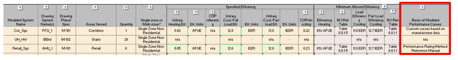
- The modeled performance curves reflect variations in efficiency and capacity of the specified equipment at the range of operating conditions. The basis of the modeled performance curves must be specified in the last column of Table 1a on the Baseline HVAC PRM tab for PRM projects and on the Budget HVAC ECB tab for ECB projects. The curves from the ANSI/ASHRAE/IES Standard 90.1-2016 Performance Rating Method Reference Manual or more recent version should be used; projects with other sources selected may be flagged for further review. The modeled performance curves may be verified by checking that, based on the simulation reports, the realized annual average efficiency is similar to the rated IEER of the unit. For alterations subject to 90.1 2022 Section G3.3 (i.e., Minor Alterations) refer to the Notes section under Table 1a on the Proposed HVAC tab for clarifications as to the performance curves modeled in the baseline design model.
AHVAC11–B,P Modeled heating and cooling efficiency of the air-side systems reflect values reported in the Compliance Form
Review Tips
-
Use simulation reports to spot-check that the modeled cooling and heating efficiencies is as
reported for selected air-side systems as follows:
- COPnfcooling and COPnfheating reported in the Compliance Form is aligned with the simulation reports. The reported values are found in Table 1a of the Proposed HVAC for the proposed systems and in Table 1a of the Budget HVAC ECB/ Baseline HVAC PRM tabs for budget/baseline systems. Refer to/request supplemental documentation for alterations subject to 90.1 2022 Section G3.3 (i.e., Minor Alterations) for modeled baseline values.
-
Warm-air furnaces may have efficiency expressed as the Annual Fuel Utilization
Efficiency (AFUE), thermal efficiency (Et) or combustion efficiency (Ec). The
conversions below (from the Performance Rating Method Reference Manual) may be used if
the efficiency input supported by the simulation tool differs from the efficiency metric
available from the manufacturer for the specified equipment:
Et=0.0051427 x AFUE + 0.3989Et=Ec – 2%
The calculations are performed automatically for the baseline/budget systems and results are shown in Table 1a of the Budget HVAC ECB/ Baseline HVAC PRM tabs.
AHVAC12–B,P Annual average realized DX cooling and heating system efficiencies reflect expected performance at the range of actual conditions
Review Tips
- Background: The average annual cooling efficiency is the ratio of the annual cooling load to the annual cooling energy from the simulation output reports. It reflects the realized performance of the modeled system. Most simulation tools used for compliance modeling describe cooling system performance through the rated efficiency and performance curves that capture impact of part load, indoor and outdoor temperatures and various other design, operational and site parameters on system performance. The realized efficiency is typically different from the rated full load efficiency and is similar to IEER (part load efficiency).
- The check should be performed when cooling is an impactful end use on the project or when heat pumps account for a significant share of heating capacity.
- Calculate the realized efficiency based on the modeling results for a sample of air-side systems and compare the result to the rated part-load efficiency. Systems with substantial difference between modeled and rated part load efficiency should be flagged. Lower than expected realized efficiency for the baseline/budget systems and higher than expected realized efficiency for the proposed systems is of especial concern since it may be due to modeling discrepancies and lead to overly optimistic compliance outcomes.
- Common Mistakes
- Using inappropriate performance curves, such as software default performance curves instead of the performance curves provided in the PRM RM.
-
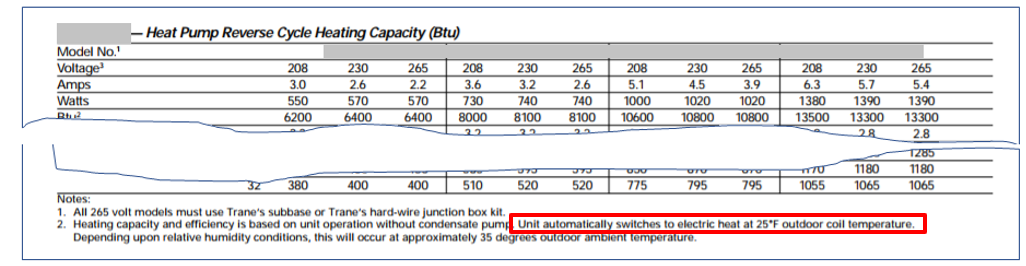
Modeled heat pumps incorrectly account for performance degradation at low ambient
temperatures including the use of electric resistance heat. In a heating-dominated
climate, the average realized heat pump heating efficiency is expected to be worse than
the manufacturer’s rating at 47°F and slightly over the manufacture’s rating 17°F. For
units that operate in electric resistance mode below 40 F, the average efficiency will
be slightly higher than 1.
For example, air-source heat pumps (ASHPs) often operate in the heat pump mode only down to 35F and use electric resistance heating at the lower temperatures. Reviewers should request equipment cut sheets documenting low-temperature performance of the specified equipment, because it has significant impact on heating energy use and should be reflected in the average annual realized efficiency including heat pump supplement. See sample air-source heat pump specification below describing low temperature operation.
AHVAC13–B,P Average realized heating efficiency of air-side systems reflect expected performance.
Review Tips
- Background: The average heating system efficiency is the ratio of the annual heating load to the annual heating energy use of the system, with both values taken from the simulation output reports.
- The check should be performed when heating is an impactful end use. Calculate the realized efficiency based on the modeling results for a sample of air-side systems and compare the result to the rated part-load efficiency. Systems with substantial difference between modeled and rated part load efficiency should be flagged. Lower than expected realized efficiency for the baseline/budget systems and higher than expected realized efficiency for the proposed systems is of especial concern since it may be due to modeling discrepancies and lead to overly optimistic compliance outcomes.
- For warm air furnaces with an AFUE rating, the average realized efficiency is expected to be similar to AFUE. For other units, the average realized efficiency is expected to be about 5% below thermal efficiency, based on the furnace part load efficiency curves included in the Performance Rating Method Reference Manual. For example, if a unit is rated at Ec=80%, its Et = Ec – 2% = 78% and the average efficiency is expected to be ~ 73%. The average efficiencies exceeding the above estimates should be flagged.
-
Efficiency degradation at part load is not prescribed in 90.1, but the average annual baseline
(budget) efficiency below 75% should be flagged in the review. Table 14 shows efficiency
degradation based on the performance curves in the Performance Rating Method Reference Manual.
For example, furnace operates at 74% efficiency when the heating load is equal to half of
its rated capacity.
Table 14: Fossil Fuel Furnace Part Load Efficiency Degradation
% of Design Load Qpartload/Qrated 100% 90% 80% 70% 60% 50% 40% 30% 25% Realized Furnace Efficiency 80% 79% 78% 77% 76% 74% 73% 71% 70%
- Common mistakes
- Modeling the baseline/budget systems as having continuously on pilot light.
For heat pumps: Use annual totals for heating equipment load, heating input kWh”, “supply fan kWh”.
AHVAC14-P Design supply, return, relief and exhaust fans’ flow rates reported in the Compliance Form are as specified in the Design Documents
Review Tips
-
Design flow rates for the specified supply, return, relief and exhaust fans are listed in Table
2a of the Proposed HVAC tab. Cross-check Compliance Form inputs with the information provided in
the mechanical schedules for a sample of specified systems to ensure alignment.
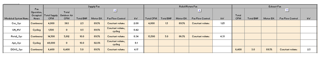
The figure below illustrates how fan system performance is typically shown in the design documents.
AHVAC14–B Baseline/budget design fans flow rates reported in the Compliance Form are established correctly
90.1 2016 and 2019/2022 ECB
Section 11.5.2 g/12.5.2 g: Design supply air rates for the budget building must be based on a supply-air-to-room-air temperature difference of 20°F. If return or relief fans are specified in the proposed design, the budget building design must also have the same fan type sized for the budget system supply fan air quantity less the minimum outdoor air, or 90% of the supply fan air quantity, whichever is larger.
90.1 2016 PRM
The efficiency values included in 90.1 Tables G3.5.1 through G3.5.6 do not include supply fan energy so no adjustments are required.
90.1 2016 and 2019
Section G3.1.2.8: Design supply airflow rates must be based on a supply-air-to-room temperature difference of 20°F or the minimum baseline ventilation rate, whichever is greater. If return or relief fans are specified in the proposed design, the baseline building design must also have fans serving the same functions and sized for the baseline system supply fan air quantity less the minimum outdoor air, or 90% of the supply fan air quantity, whichever is larger.
90.1 2022 PRM
G3.2 New Construction/Major AlterationsSection G3.2.2.7: Same as the requirement for the 90.1 2016 and 2019 PRM in Section G3.1.2.8
G3.3 Minor Alterations
The design supply air flowrates for systems included in the scope of retrofit for alterations
subject to 90.1 2022 Section G3.3 (i.e., Minor Alterations) shall be autosized using the same
supply-air-to-room temperature difference as was used for sizing in the design or the minimum
baseline ventilation rate, whichever is greater. If this design sizing parameter information is
unavailable, then design supply airflow rates can be autosized based on a supply-air-to-room
temperature difference of 20°F or the minimum baseline ventilation rate, whichever is greater.
If return or relief fans are specified in the proposed design, the baseline building design must
also have fans serving the same functions and sized for the baseline system supply fan air
quantity less the minimum outdoor air, or 90% of the supply fan air quantity, whichever is larger.
Review Tips – ECB
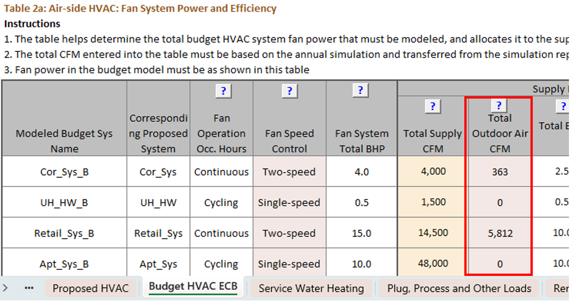
- Design flow rate of the budget systems is reported in Table 2a of the Budget HVAC ECB tab.
-
Supply fan flow is a user input and must reflect the value determined through the simulation.
Relief/return and exhaust flows are auto populated in the Compliance Form based on the 90.1
requirements quoted above. Spot-check supply fan flow rates for a sample of air-side systems
compared to typical show in Table 15 and outliers should be flagged.
Table 15: Typical Supply Air Flow Rates*
*From ASHRAE Pocket Guide for Heating, Ventilation, Refrigeration (I-P Edtion), 7th Edition (see latest edition here)Occupancy Type Supply Air CFM/SF Apartment high-rise 0.5 – 0.8 Office buildings 0.8 – 1.6
- Common Mistakes
- The causes for higher-than-expected design flow rates are similar to those that lead to exaggerated cooling loads described in AHVAC05-B.
- Sizing flow based on supply air to room air temperature difference less than 20°F exaggerates the flow.
- For Appendix G, exaggerated design flow rate may also be caused by applying the over-sizing factor in 90.1 Section G3.1.2.2 to design flows in addition to coil capacities, which is incorrect – only coil capacities must be oversized.
Review Tips – PRM
- Design flow rate of the baseline systems is reported in Table 3b of the Baseline HVAC PRM tab. Refer to/request supplemental documentation for alterations subject to 90.1 2022 Section G3.3 (i.e., Minor Alterations) for modeled baseline values. The flows may be compared to typical shown in Table 15 above.
- Common Mistakes
- Refer to common mistakes listed for this check under ECB.
- The exaggerated design flow rate may also be caused by applying the over-sizing factor in 90.1 Section G3.1.2.2 to design flows in addition to coil capacities, which is incorrect – only coil capacities must be oversized.
AHVAC15-P Design supply, return, relief and exhaust fan power reported in the Compliance Form is as specified in the design documents
Review Tips
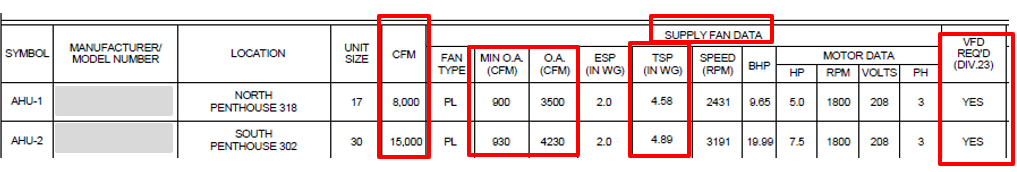
- Design power of the specified supply, return, relief and exhaust fans is listed in Table 2a of the Proposed HVAC tab for all specified systems. Cross-check Compliance Form inputs with the information provided in the mechanical schedules for a sample of the specified systems to ensure alignment.
- Common Mistakes
- External static pressure (ESP) is used in lieu of the total static pressure (TSP). This significantly underestimates the proposed fan energy.
- Only supply fan power is entered. Other specified fans such as return, exhaust and relief omitted from the template.
- Indoor fans for split air source heat pump and variable refrigerant flow heat pump systems excluded or incorrectly entered under the “Terminal Unit” columns. The “Terminal Unit” columns are for terminal units in multi-zone variable air volume systems (i.e., VAV boxes).
AHVAC15-B Baseline/budget fan power reported in the Compliance Form is established correctly
90.1 2016 and 2019/2022 ECB
Section 11.5.2 h/12.5.2 hBHP per CFM of supply air, including the effect of belt losses but excluding motor and motor drive losses must be the same as the proposed design or up to the limit prescribed in 90.1 Section 6.5.3.1, whichever is smaller. If this limit is reached, BHP of each fan must be proportionally reduced until the limit is met. Fan electrical power must be determined by dividing the calculated fan BHP by the minimum motor efficiency in 90.1 Section 10.4.1 for the appropriate motor size for each fan.
90.1 2016 and 2019 PRM
Section G3.1.2.9The section provides formulas for calculating the total combined power of supply, return, exhaust and relief fans excluding fan-powered VAV boxes. For Systems 3 – 8 and 12 - 13, the baseline BHP allowance provided in 90.1 Table G3.1.2.9 may be increased to account for certain design features included in the proposed design. Common examples of the allowed baseline pressure drop adjustments include proposed systems with MERV 9 or higher air filters, sound attenuation devices and ducted returns (90.1 Table 6.5.3.1-2).
90.1 2022 PRM
G3.2 New Construction/Major AlterationsRequirements are the same as for the 90.1 2016 and 2019 PRM above.
G3.3 Minor Alterations
Systems and equipment included in the scope of retrofit for alterations subject to 90.1 2022
Section G3.3 (i.e., Minor Alterations) are required to be modeled with baseline fan power as
described above for 90.1 2016 and 2019/2022 ECB with the exception that when a proposed design
includes energy recovery, but it is not required in the baseline building design per 90.1
Sections 6.1.4 and 6.5.6, the fan power of the baseline system shall be equal to either the
proposed design system or the fan power limit in Section 6.5.3.1 calculated without fan power
credit for energy recovery, whichever is less. Based on the language in 90.1 Section
6.1.4, 90.1 Section 6.5.6 requirements would only be relevant to the baseline when an
alteration includes new cooling systems installed to serve previously uncooled spaces.
Review Tips – 90.1 ECB
-
Fan power for individual HVAC systems in the budget design is included in Table 2a of the
Budget HVAC ECB tab and is calculated automatically by applying the applicable 90.1 rules
quoted above. The total budget power by fan type is shown in Table 3. Since these values are
auto populated in the Compliance Form, they do not need to be checked.

Review Tips – PRM
- Refer to 90.1 2022 Section G3.3 Performance Calculations for Other Alterations for the location of baseline fan power in the Compliance Form for alterations subject to 90.1 2022 Section G3.3 (i.e., Minor alterations).
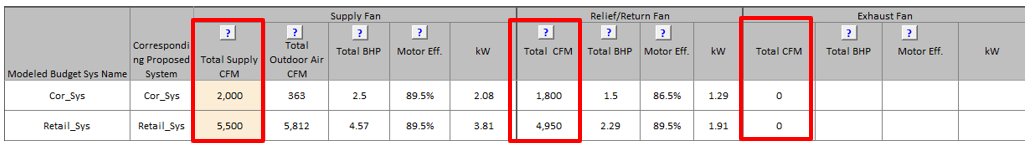
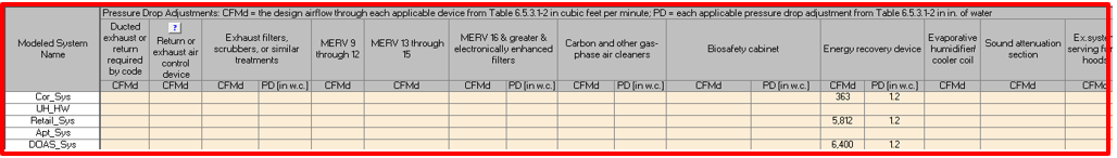
-
The allowed pressure drop adjustments for calculating the total baseline fan power allowance
are entered in Table 2a of the Baseline HVAC PRM tab. Spot-check sample systems to confirm
that the design flow rate CFMD entered for each category includes only flow to
the zones that include the allowed device in the proposed design. For example, if in the
proposed design sound attenuation is specified only for some of the zones, CFMD
entered in the sound attenuation column must include only supply flow to these zones in the
baseline design and not the total supply flow of the baseline system. Spot-check should
focus on baseline systems with high CFMD
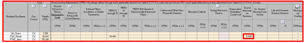
Confirm that all devices included in Table 2a for the baseline are also included in the Proposed HVAC tab Table 3, and the total CFMD are similar between the baseline and proposed design except for energy recovery and ducted return as described in the Common Mistakes below.
-
The total design power of the baseline supply, return, relief and exhaust fans is shown in
the second half of Table 2a of the Baseline HVAC App G. The total for all fans is calculated
by applying the formulas in G3.1.2.9 to the user-specified supply flow rate accounting for
the applicable pressure drop adjustments discussed above, and is allocated to the baseline
supply, return, relief and exhaust fans based on user-entered values in the % of Total Fan
Power columns for the corresponding fans.
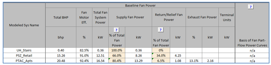
Optionally, cross-check user-specified allocation of fan power between supply, return/relief and exhaust fans for a sample of systems to verify consistency with how the fan power is allocated to these fans in the proposed design.
-
Common Mistakes for the PRM (excluding alterations subject to 90.1 2022 G3.3)
- CFMD is entered as a baseline system pressure drop adjustment in Table 2a for systems that have exhaust air energy recovery in the proposed design, but no exhaust air energy recovery in the baseline. Based on Table G3.1.2.9 Note 2, the pressure drop credit may only be claimed when the baseline system has energy recovery.
- CFMD is entered in Table 2a for the baseline systems that have ducted return in the proposed design, but the ducted return is not required by applicable code. In these cases, baseline should be assumed to have no ducted return.
- Power of exhaust or DOAS fans specified in the proposed design is added to the baseline fan power allowance determined following 90.1 Section G3.1.2.9. Instead, the baseline fan power allowance is inclusive of all baseline fans.
AHVAC16-P Air flow and supply temperature controls reported in the Compliance Form for the proposed design are as specified in the design documents
Review Tips
- Air flow control method for each specified air-side HVAC system is reported in Table 1a of the
Proposed HVAC tab.
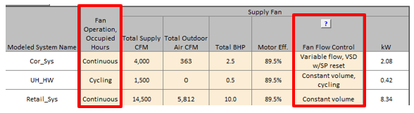
- Additional details are included in Table 4 of the Proposed HVAC tab.
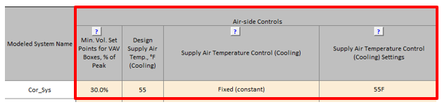
Cross-check Compliance Form inputs with the information provided in the mechanical schedules and specifications for a sample of the specified systems to ensure alignment.
- Refer to Table 2b for a birds-eye view of the specified fan systems and controls.
AHVAC16–B Baseline (budget) air flow and supply temperature control is established correctly
Review Tips
90.1 2016 and 2019/2022 ECB
Section 11.5.2/12.5.2: Supply and return/relief system fans shall be modeled as operating at least whenever the spaces served are occupied, except as specifically noted in 90.1 Table 11.5.2-1. Minimum volume set points for VAV reheat boxes shall be 30% of zone peak airflow or the minimum ventilation rate, whichever is larger (90.1 Table 11.5.2-1/12.5.2-1 Note b). Baseline supply, return, or relief fans in Systems 1-4 must be modeled assuming a variable-speed drive and fan part-load performance in 90.1 Section G3.1.3.15/G3.2.3.15 (see Table 6 below). If the proposed design’s system has a DDC at the zone level, static pressure set point reset based on Section 6.5.3.2.3 must be modeled in the budget design.
Table 11.5.2 – 1 Note b/ Table 12.5.2 – 1 Note b: The supply air temperature for cooling shall be reset higher by 5°F under the minimum cooling load conditions for all budget VAV systems with reheat.
90.1 2016 and 2019 PRM
Table G3.1.3.15: For baseline Systems 5 and 7, the minimum volume set points for VAV reheat boxes must be 30% of zone peak airflow, the minimum outdoor airflow rate, or the airflow rate required to comply with the applicable codes or accreditation standards, whichever is larger. The part load performance of VAV system supply fans must have the part-load performance characteristics specified in 90.1 Table G3.1.3.15. There is no static pressure set-point reset in the baseline.
Section G3.1.3.12: The air temperature for cooling shall be reset higher by 5°F under the minimum cooling load conditions for Systems 5 – 8.
90.1 2022 PRM
G3.2 New Construction/Major Alterations
Table G3.2.3.15 and Section G3.2.3.12 requirements are the same as for the
analogous sections in the 90.1 2016 and 2019 PRM as described above.
G3.3 Minor Alterations
Systems and equipment included in the scope of retrofit for alterations subject to 90.1 2022
G3.3 (i.e., Minor Alterations) are required to model baseline systems as minimally compliant
with 90.1 Sections 6.5.3.2.1 and any other relevant sections as applicable based on the
requirements of 90.1 Section 6.1.4.
Review Tips
-
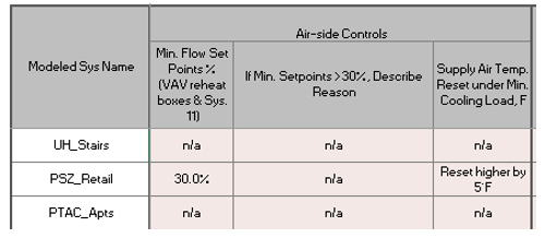
PRM: Baseline flow and temperature controls for the baseline VAV systems is shown in Table
3a of the Baseline HVAC PRM tab. The values are set automatically based on the relevant 90.1
rules quoted above and should only be checked if any auto-populated defaults
are overwritten. (Such values will be shown in brown font.) Refer to the Notes sections
under Table 4 on the Proposed HVAC tab for baseline modeling inputs for alterations subject
to 90.1 2022 Section G3.3 (i.e., Minor alterations).
- ECB: Fan speed control of the budget HVAC systems is shown in Table 2a of the Budget HVAC ECB tab. Minimum flow setpoints in temperature reset under minimum cooling load conditions for VAV systems are shown in Table 3. The values are set automatically based on the relevant 90.1 rules quoted above and should only be checked if any auto-populated defaults are overwritten. (Such values will be shown in brown font.)
AHVAC17-P Fan power performance curves reported for the proposed design in the Compliance Form are based on an approved source
Review Tips
- The modeled performance curves reflect correlation between energy used by the fan and flow rate relative to the design maximum. The input applies only to the variable flow systems, and must be provided in the last column of Table 2a of the Proposed HVAC tab. The default VAV performance curves included in 90.1 Table G3.1.3.15 (Table G3.2.3.15 in 90.1 2022) and the fan curves provided in ANSI/ASHRAE/IES Standard 90.1-2016 Performance Rating Method Reference Manual, Table 50 should be used, depending on the specified flow control strategy.
- The curves should be reviewed for a sample of HVAC systems if ventilation fans are an impactful end use and performance curves other than 90.1 default are specified.
- Supporting documentation must be included in the submittal if the basis of the performance curves is specified as “Other” in Table 2a. Refer to the Submittal Checklist tab #18 to confirm that the necessary documentation is included in the submittal.
AHVAC17-B Fan power performance curves used in the simulation are based on an approved source
Review Tips
- The fan performance curves for VAV systems are specified in the last column of Table 2a Baseline HVAC PRM tab or Budget HVAC ECB tab and must be based on 90.1 Table G3.1.3.15 (Table G3.2.3.15 in 90.1 2022). The values are auto-populated and do not need to be checked.
- Refer to the Notes sections under Table 2a on the Proposed HVAC tab for modeled baseline fan curves for alterations subject to 90.1 2022 Section G3.3 (i.e., Minor alterations). If the fan curves differ from Table G3.2.3.15 or the fan curves in the PNNL PRM RM request documentation from the submitter to justify the modeled curves.
AHVAC18– B, P Fan power, flow rate and controls are modeled as reported in the Compliance Form
Review Tips
-
Spot-check simulation reports to verify that the following simulation inputs reflect information
provided in the Compliance Form:
- Power of supply, exhaust, return and relief fans (Watt)
- Supply, exhaust, return and relief flow (CFM)
- Minimum flow fraction for representative thermal blocks
The review should focus on HVAC systems with large air flow.
AHVAC19–B, P Modeled peak demand of ventilation fans is generally consistent with design fan power and control reported in the Compliance Form
Review Tips
-
Spot-check simulation reports for a sample of HVAC systems with high air flows in the proposed
and baseline/budget design to find the non-coincident peak demand for the system fans. Compare
the simulated values to the estimates obtained as described below. Flag proposed systems with
the simulated non-coincident peak demand is lower than estimated. Flag baseline/budget systems
that have simulated non-coincident peak demand that is higher than expected.
- For the constant volume systems, the peak demand is equal to the design fan kW.
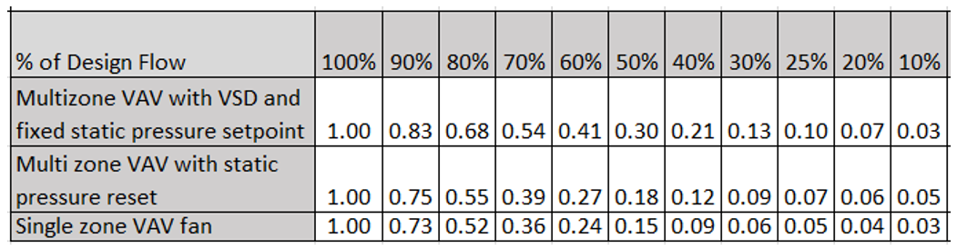
- Variable volume system fans often reach the maximum flow no greater than 70% of the design CFM, drawing approximately 50% of the design power (Table 16).
-
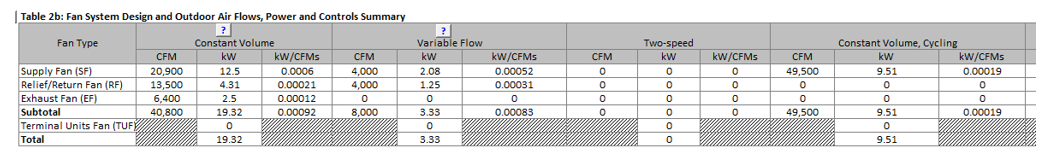
These relationships may also be used to verify fan energy use patterns for the project as a
whole, for example to confirm that the fan power reported in Table 3b of the Baseline HVAC PRM
tab (shown below) or Table 2b of the Budget HVAC ECB tab is generally consistent with
non-coincident peak demand reported in the Compliance Calculations tab Table 2 for both
baseline/budget and proposed designs. Refer to
90.1 2022 Section G3.3 Performance Calculations for Other Alterations
for the location of baseline fan power in the Compliance Form for alterations subject to 90.1
2022 Section G3.3 (i.e., Minor alterations).

AHVAC20–B, P Modeled equivalent full load hours of the ventilation fans are as expected.
Review Tips
- Background: The EFLH of the fan system is the ratio of the fan energy use to fan peak demand. If a project has only the constant volume systems that run continuously when the building is occupied, the fan EFLH will be slightly higher than the number of hours per year when the building is occupied, accounting for the energy consumed by the cycling fans during unoccupied hours and system runtime to bring the building to occupied temperatures in the morning.
-
Calculate EFLH for a sample of baseline/budget systems with high fan power reported in
Table 2a of the Baseline HVAC PRM or Budget HVAC ECB tabs (see Table 3 on the Proposed HVAC tab
and the Notes section under the table for alterations subject to 90.1 2022 Section G3.3) and
check for the following patterns:
- Part load performance of the baseline VAV systems are shown in the second row of Table 6 (Multizone VAV with VSD and fixed static pressure setpoint). If all baseline (budget) systems are variable air volume, the average flow during occupied hours is typically about 60% of the design flow, with the fan system drawing ~41% of the design power based on Table 6. Thus, the EFLH are expected to be ~ 41% of the number of occupied hours per year.
- For the constant volume systems, EFLH are expected to be slightly higher than the total number of hours building is occupied, since the baseline/budget systems must be modeled as running continuously during occupied hours and cycle with load during un-occupied hours.
The baseline fan EFLH that exceed expectation should be flagged and may indicate incorrect modeled fan system control.
Table 16: Fraction of VAV Fan Power at Reduced Flow (PRM RM)
Common Mistakes:
- Modeled minimum flow for VAV systems are higher than 30%
- Fans are modeled as running continuously instead of cycling with load during unoccupied hours.
-
Calculate EFLH for a sample of proposed systems with high fan power reported in Table 2a of the
Proposed HVAC tab and check for the patterns described for the baseline/budget systems. The
proposed fan system EFLH that are lower than expected should be flagged. Common mistakes include
the following:
- Modeling fans that supply ventilation air as cycling with load instead of running continuously during occupied hours results in significantly under-estimate fan, heating and cooling energy use.
AHVAC21-P Air-side economizers reported in the Compliance Form are as specified in the design documents
Review Tips
- The specified economizer controls are reported in Table 4 of the Proposed HVAC tab. Cross-check
the provided information with the design documents for a sample of HVAC systems to ensure
alignment.
- The check should be completed where cooling is an impactful end use except in climate zones 0 and 1.
- Projects without economizers are expected to have higher cooling energy use in fall, winter and spring and higher simultaneous heating & cooling during these months.
AHVAC21-B Air-side economizers reported in the Compliance Form for the baseline/budget systems are established correctly
90.1 2016 and 2019 ECB
Section 11.5.2(e)Each system in the budget building must have the same economizer type (outdoor air or water) as the corresponding system in the proposed design. If economizer is not specified in the proposed design, an air-side economizer must be modeled in the budget building where required in Section 6.5.1. For example, in New York climate zones 4A, 5A, 6A economizers must be modeled for budget systems with cooling capacity of 54 kBtu/hr or greater, unless exceptions apply. The high-limit shutoff must be modeled per 90.1 Table 11.5.2-4
90.1 2022 ECB
Section 12.5.2(e)Each system in the budget building must have an air-side economizer modeled where required in Section 6.5.1 based on the capacity establish in 12.5.1(i). For example, in New York climate zones 4A, 5A, 6A economizers must be modeled for budget systems located outside of the building with cooling capacity of 33 kBtu/hr or greater, unless exceptions apply. The high-limit shutoff must be modeled per 90.1 Table 11.5.2-4.
90.1 2016 and 2019 PRM
Section G3.1.2.6: Economizers must not be included in baseline HVAC System 1, 2, 9, and 10. Air economizers must be included in baseline HVAC Systems 3 through 8 and 11, 12, and 13 (unless exception to 90.1 Section G3.1.2.6 apply), based on climate as specified in 90.1 Table G3.1.2.6. For example, projects in New York climate zone 4A do not have an economizer in the baseline. Projects in climate zone 5A and 6A must be modeled with an economizer in the baseline. Economizer high-limit shutoff temperature must be modeled per Table G3.1.2.7.
90.1 2022 PRM
G3.2 New Construction/Major AlterationsSections G3.2.2.5, G3.2.2.6 requirements are the same as for the 90.1 2016 and 2019 PRM described above.
G3.3 Minor Alterations
Systems and equipment included in the scope of retrofit for alterations subject to 90.1 2022
Section G3.3 (i.e., Minor Alterations) are required to model an air-side economizer where
required by Section 6.1.4. For example, for a project located in climate zone 4A in which a new
cooling system is installed to serve previously uncooled spaces the baseline requirements would
be established according to 90.1 Section 6.1.4.2 which references all 90.1 Section 6 mandatory
and prescriptive requirements including 90.1 Section 6.5.1 (Economizers). Because the project is
in climate 4A economizers must be modeled for baseline systems located outside of the building
with a cooling capacity of 33 kBtu/hr or greater based on 90.1 Section 6.5.1 requirements
(unless exceptions apply). The high-limit shutoff for this example would be modeled based on the
minimum requirements associated with 90.1 Table 6.5.1.1.3.
Review Tips
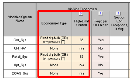
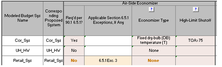
- Air-side economizers are shown in Table 3a of the Baseline HVAC PRM and in Table 3 of the Budget
HVAC ECB (shown below). The values are auto-populated based on the applicable rules of the ECB
or PRM. Over-written defaults are shown in brown font and should be verified by reviewer. Refer
to
90.1 2022 Section G3.3 Performance Calculations for Other Alterations
for review tips for alterations subject to 90.1 2022 Section G3.3 (i.e., Minor alterations).
AHVAC22-P, AHVAC22-B Air-side economizers in the baseline/budget and proposed design is modeled as reported in the Compliance Form
Review simulation reports to verify that air-side economizer is modeled as reported in the Compliance Form.
AHVAC23–P Design ventilation rates reported in the Compliance Form are consistent with the design documents
Review Tips
-
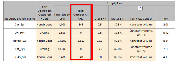
Outdoor air rates are reported in Table 2a of the Proposed HVAC tab. Cross-check reported rates
with the design documents for a sample of specified systems to verify alignment.
AHVAC23–B Baseline/budget ventilation rates reported in the Compliance Form are established correctly
Review Tips
-
Outdoor air rates are reported in Table 2a of the Proposed HVAC tab. Cross-check reported rates
with the design documents for a sample of specified systems to verify alignment.
90.1 2016 ECB
90.1 Section 11.5.2 d: Minimum outdoor air ventilation rates must be the same in the budget building design and proposed design.
90.1 2019/2022 ECB
90.1 Section 11.5.2 d/12.5.2 d: Minimum outdoor air ventilation rates must be the same in the budget building design and proposed design with the following exceptions.
- When modeling demand control ventilation in the proposed design for spaces where demand control ventilation is not required per Section 6.4.3.8.
- Where the minimum outdoor air intake flow in the proposed design is provided in excess of the amount required by Section 6.5.3.7/6.5.3.8, the budget building design shall be modeled to reflect the minimum amount required by Section 6.5.3.7/6.5.3.8.
90.1 2016 and 2019 PRM
90.1 Section G3.1.2.5: Minimum ventilation system outdoor air intake flow must be the same for the proposed design and baseline building design, with the following exceptions.
- Baseline may have higher OA flow compared to the proposed design if the following applies:
- The proposed system has Demand Control Ventilation AND the outdoor air capacity is less than or equal to 3000 cfm serving areas with an average design capacity of 100 people per 1000 ft2 or less (90.1 Section G3.1.2.5 Exception 1).
- The proposed system has zone air distribution effectiveness Ez > 1.0 based on ASHRAE Standard 62.1 Table 6-2 (90.1 Section G3.1.2.5 Exception 1).
- The baseline must have a lower OA flow compared to the proposed design if the specified ventilation rate exceeds the minimum required by the applicable building code (90.1 Section G3.1.2.5 Exception 3). Ventilation rates may also differ between the baseline and proposed design for systems serving laboratory spaces (90.1 Section G3.1.2.5 Exception 4).
90.1 2022 PRM
G3.2 New Construction/Major Alterations90.1 Section G3.2.4: Requirements are the same as the 90.1 2016 and 2019 PRM described above.
G3.3 Minor Alterations
Systems and equipment included in the scope of retrofit for alterations subject to 90.1 2022
Section G3.3 shall be modeled the same in the baseline and proposed with the exception of the
following scenarios:
-
The alteration includes new cooling systems installed to serve previously uncooled spaces.
In this case the baseline shall be modeled as minimally compliant with Standard 90.1-2022
Section 6.5.3.8 with the same feature as the proposed design. Where the proposed design does
not include one of these features it is recommended that the baseline be modeled according
to Standard 90.1-2022 Section 6.5.3.8 option a with no more than 135% of the required
minimum outdoor air rate modeled in the baseline.
Standard 90.1-2022 Section 6.5.3.8 states that the required minimum outdoor air rate is the larger of the minimum outdoor air rate or the minimum exhaust air rate required by Standard 62.1, Standard 62.2, Standard 170, or applicable codes or accreditation standards. The section also requires that outdoor air ventilation systems comply with one of the following:
- Design minimum system outdoor air provided shall not exceed 135% of the required minimum outdoor air rate.
- Dampers, ductwork, and controls shall be provided that allow the system to supply no more than the required minimum outdoor air rate with a single set-point adjustment.
- The system includes exhaust air energy recovery complying with Section 6.5.6.1.
- If the following conditions are met,
- DCV is specified in the proposed design,
- Standard 90.1-2022 Section 6.4.3.8 is applicable based on the scope of the alteration and the requirements of 90.1-2022 Section 6.1.4, and
- DCV is not required to be modeled in the baseline according to 90.1 Section 6.4.3.8
then ventilation air flow may differ between the baseline and proposed due to DCV. See the Design Ventilation Rate: Demand Control Ventilation descriptor for the requirements of 6.4.3.8.
Review Tips - 90.1 ECB
- Baseline ventilation rates are reported in Table 2a of Budget HVAC ECB tab and is set to be
equal to the corresponding budget system. Over-written defaults are shown in brown font and
should be verified by reviewer.
Review Tips - 90.1 PRM
- Refer to 90.1 2022 Section G3.3 Performance Calculations for Other Alterations for review tips for alterations subject to 90.1 2022 Section G3.3
-
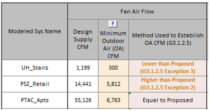
Baseline ventilation rates are reported in Table 3a of Baseline HVAC PRM tab. For each
baseline system, the modeled ventilation rate must be provided, and it must be stated
whether that ventilation rate is equal to the ventilation provided to the corresponding
HVAC zones in the proposed design (which is the default selection) or whether it deviates
from the proposed design due to exceptions to G3.1.2.5/G3.2.2.4.
-
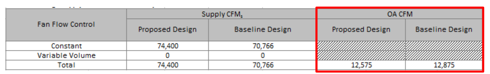
Table 3b shows side-by-side the total OA rate reported in the Compliance Form for the
baseline and proposed design. Confirm consistency between Table 3a are 3b. For example, if
Table 3a indicates that the ventilation rate in all baseline systems is modeled as “Equal
to Proposed”, the baseline and proposed rates are expected to be the same in Table 3b.
- Common Mistakes
- It is not uncommon for specified ventilation rates to exceed the minimum required. In this case, the baseline ventilation would be lower than what is specified in the proposed design, but this penalty is often not modeled. For example, based on the NYS Mechanical Code, the minimum ventilation rate in the corridors of apartment buildings is 0.06 CFM/ft2. If the specified ventilation exceeds this minimum, the ventilation rate in the baseline design must be modeled as 0.06 CFM/ft2. Ventilation in the proposed design must be as specified and will be higher than in the baseline.
AHVAC24–P Demand control ventilation reported in the Compliance Form for the proposed design is consistent with the design documents
Review Tips
-
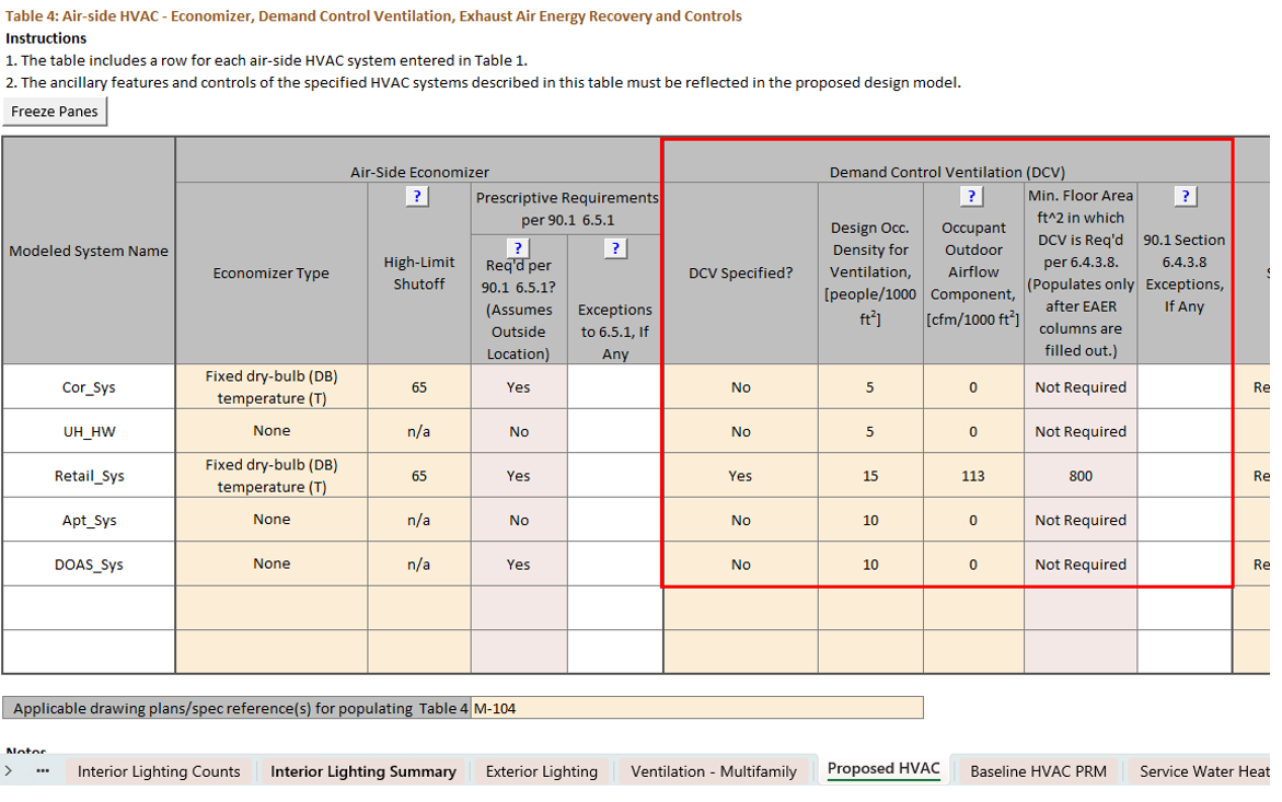
Demand control ventilation (DCV) is reported in Table 4 of the Proposed HVAC tab. Cross-check
information provided in the table with the design documents for a sample of specified systems to
verify alignment.

AHVAC25–P Demand control ventilation reported in the Compliance Form for the proposed design meets mandatory requirements in 90.1 Section 6
Review Tips
-
Demand control ventilation may be required by 90.1 Section 6.4.3.8. These requirements are
mandatory and thus DCV must be specified for systems where it is required. The applicability of
the requirements are established automatically in Table 4 of the Proposed HVAC tab based on
user-entered design and OA flow rates and occupant density. The default may be over-written by
user if exceptions to 90.1 Section 6.4.3.8 apply. The over-written values are shown in bold
brown font and applicable exceptions must be listed. Verify that DCV is specified where
required.
AHVAC25–B Demand control ventilation reported in the Compliance Form for the baseline/budget design is established correctly.
90.1 2016, 2019, and 2022 ECB
See AHVAC23–B for relevant 90.1 sections.
90.1 2016, 2019, and 2022 PRM
See AHVAC23–B for relevant 90.1 sections.
Review Tips
- Demand Control Ventilation requirements applicable to each baseline/budget HVAC system are shown in Table 3 of Budget HVAC ECB tab or Table 3a of the Baseline HVAC PRM tab. The values are auto-populated in the Compliance Form based on user-specified maximum occupant density. Overwritten defaults should be reviewed to verify that the exception referenced in the Compliance Form is properly applied. Refer to 90.1 2022 Section G3.3 Performance Calculations for Other Alterations for review tips for alterations subject to 90.1 2022 Section G3.3 (i.e., Minor alterations).
AHVAC26– B, P Ventilation rate and control are modeled as reported in the Compliance Form
Review Tips
- Spot-check a sample of air-side HVAC systems to confirm that the minimum design ventilation rate CFM and DCV controls are modeled as reported in the Compliance Form for the corresponding systems.
AHVAC27–P Exhaust air energy recovery reported in the Compliance Form reflects design documents
Review Tips
-
Exhaust air energy recovery is reported in Table 4 of the Proposed HVAC tab. Cross-check
information provided in the table with the design documents for a sample of specified systems to
verify alignment.

AHVAC27–B Exhaust air energy recovery reported in the Compliance Form for the budget/baseline design is established correctly
90.1 2016 and 2019/2022 ECB
Section 11.5.2 d/12.5.2 d: Exhaust air heat recovery must be included in the budget building systems if required by 90.1 Section 6.5.6.1. For example, for 90.1 2019 and 2022 projects, all systems in climate zones 4A, 5A, 6A operating 8,000 or more hours per year, serving nontransient dwelling units, with 200 CFM or greater supply CFM, and a % outdoor air fraction of 10% or greater must have energy recovery modeled in the budget design model (90.1 Section 6.5.6.1.2), unless exceptions apply.
90.1 2016 and 2019 PRM
Section G3.2.2.9: Requirements are similar to the 90.1 2016 and 2019 PRM requirements described above except an exception was added for systems serving laboratory HVAC zones with a total laboratory exhaust volume greater than 15,000 cfm. These systems are not required to model exhaust air energy recovery in the baseline design model.
90.1 2022 PRM
G3.2 New Construction/Major AlterationsSection G3.1.2.10: Individual fan systems that have design supply air capacity of 5,000 cfm or greater AND a minimum design outdoor air supply of 70% or greater must have an energy recovery system with at least 50% enthalpy recovery ratio. 50% enthalpy recovery ratio means a change in the enthalpy of the outdoor air supply equal to 50% of the difference between the outdoor air and return air at design conditions. The most common exception to this rule applies to projects where the largest exhaust source is less than 75% of the design outdoor airflow and that do not have exhaust air energy recovery in the proposed design (90.1 Section G3.1.2.10 Exception 6). An example of such configuration includes rooftop units supplying ventilation in multifamily buildings, with exhaust from apartment kitchens and bathrooms via multiple rooftop exhaust fans that serve vertical stacks of apartments.
G3.3 Minor Alterations
The systems and equipment included in the scope of retrofit for alterations subject to 90.1 2022
Section G3.3 are required to model exhaust air energy recovery in the baseline model if it is
minimally required based on 90.1 Section 6.5.6 and if 90.1 Section 6.5.6 applies to the
alteration based on the language in 90.1 Section 6.1.4. Based on the language in 90.1 Section
6.1.4, 90.1 Section 6.5.6 requirements would only be applicable to the baseline when the
alteration includes new cooling systems installed to serve previously uncooled spaces.
Review Tips
- Exhaust air energy recovery that must be modeled in the budget/baseline systems is shown in Table 3 of the Budget HVAC ECB tab or Table 3a of the Baseline HVAC PRM tab. The values are auto-populated based on the applicable rules of the Energy Cost Budget and Performance Rating Methods. Over-written defaults should be verified. Refer to 90.1 2022 Section G3.3 Performance Calculations for Other Alterations for review tips for alterations subject to 90.1 2022 Section G3.3 (i.e., Minor alterations).
AHVAC28–B, P Modeled exhaust air energy recovery is as reported in the Compliance Form
Review Tips
-
Spot-check a sample of HVAC systems with the highest ventilation flow to confirm that the
exhaust energy recovery is modeled as reported in the Compliance Form including the following:
- System type (e.g. enthalpy wheel, runaround coil, heat exchanger)
- Rated recovery effectiveness
- Supply and exhaust flow through the energy recovery device
- Controls (e.g. to allow economizer operation when appropriate)
- Added static pressure drop
- Common mistakes:
- Increased static pressure drop (and increased fan energy) and parasitic losses such as energy to operate recovery wheel and to provide defrost is not included in the proposed design model, exaggerating the benefit of energy recovery.
- Modeled outdoor and exhaust air flow CFM passing through energy recovery device does not reflect design documents.
AHVAC29–P Additional HVAC efficiency measures reported in the Compliance Form are allowed for trade-off and reflect design documents
Review Tips
-
Additional HVAC Efficiency Measures inputs at the bottom of the Proposed HVAC tab may describe
additional system and components affecting HVAC energy use of the proposed design but not
covered elsewhere in the Compliance Form, such as thermal energy storage and ventilated façade.
The following must be listed for each measure:
- The key system parameters
- An explanation of the source of expected savings
- Whether the measure was modeled explicitly in the simulation tool or through exceptional calculations.
- Verify the following for each listed system and component:
- The reported measure involves systems and components are allowed for trade-offs
- That the key reported efficiency parameters reflect design documents and manufacturer literature
- The exceptional calculations are submitted as applicable and are based on peer-reviewed methods and not proprietary vendor’s tools. Also refer to checks in the Exceptional Calculations (EC) group.
AHVAC30-P Additional HVAC efficiency measures were modeled for the proposed design as described in the Compliance Form
Review Tips
- Review simulation input/output reports to confirm that additional HVAC efficiency measures reported for the proposed design in the Compliance Form are supported by the simulation tool and were modeled explicitly. Systems and components that are not explicitly supported must be reported as exceptional calculations method.
AHVAC31–B,P Modeled monthly patterns of heating and cooling loads are as expected with no excessive simultaneous heating and cooling
Review Tips
- Background
Typical single zone systems such as Appendix G Baseline System 1 – PTAC or System 3 – PSZ operate either in heating or cooling mode, thus no simultaneous heating and cooling is expected on system level. In models with only single zone systems, such as in Appendix G baseline for a multifamily building, only a minimal simultaneous heating and cooling is expected on building level – for example, on a mild spring day, PTACs in the West-facing apartments may operate in cooling mode, while PTACs in North-facing apartments may operate in heating mode.
Typical multizone systems such as Appendix G Baseline System 5 and 7 have some simultaneous heating and cooling on system level as well as building level due to reheat, however it is expected to be low due to requirements in 90.1 Appendix G that limit reheat in the baseline (e.g., requiring a supply air temperature reset to be modeled in the baseline for systems 5 through 8 and 11).
-
Check monthly pattern of heating and cooling energy use on air-side system level and building level to confirm that patterns are as expected. Excessive simultaneous heating and cooling is often the reason for heating/cooling energy use exceeding typical based on the benchmarks.
- Common Mistakes
- Section G3.1.1 Exception b (G3.2.1.2a in 90.1 2022) was not followed, which may lead to one zone having significantly higher cooling load than the rest of the zones served by the same baseline VAV system, leading to excessive reheat to prevent overcooling of those other zones.
- Temperature reset required in 90.1 Section G3.1.3.12 (G3.2.3.12 in 90.1 2022) (PRM) and 90.1 Table 11.5.2-1 Note b (Table 12.5.1-1 in 90.1 2022) (ECB) was not properly modeled.
- Supply temperature reset required during periods of low cooling load was not modeled resulting in excessive reheat.
- VAV minimum flow setpoint was not modeled as required in 90.1 Section G3.1.3.13 (G3.2.3.13 in 90.1 2022) (PRM) and 90.1 Table 11.5.2-1 Note b (Table 12.5.1-1 in 90.1 2022) (ECB).
- Minimum flow fraction was not modeled correctly on VAV systems. For example, 0.4 CFM/ft2 minimum flow may be modeled instead of 30% of the zone peak as required for Appendix G baseline VAV systems.
- Economizer was not modeled where required.